Physical electronics devices and ics miscellaneous
Direction: In the voltage regulator circuit shown below. The zener diode current is to be limited to the range 5 ≤ i Z ≤ 100 mA.

- The range of possible load current—
-
View Hint View Answer Discuss in Forum
From figure,
I = 6.3 – Vz = 6.3 – 4.8 12Ω 12 = 1.5 V = 125 mA 12 kΩ
The range of IL: when, Iz = 5 mA
IL = I – Iz = 125 – 5 = 120 mA
and range, when, Iz = 100 mA
IL = 125 – 100 = 25 mA
Hence the range of IL is 25 mA ≤ IL ≤ 120 mACorrect Option: B
From figure,
I = 6.3 – Vz = 6.3 – 4.8 12Ω 12 = 1.5 V = 125 mA 12 kΩ
The range of IL: when, Iz = 5 mA
IL = I – Iz = 125 – 5 = 120 mA
and range, when, Iz = 100 mA
IL = 125 – 100 = 25 mA
Hence the range of IL is 25 mA ≤ IL ≤ 120 mA
- In the voltage regulator circuit shown below. The power rating of zener diode is 400 mW. The value of RL that will establish maximum power in Zener diode is—

-
View Hint View Answer Discuss in Forum
Iz (max) = P = 400 mW = 40 mA VZ 10 V Iz + IL = 20 – VZ = 20 - 10 = 45 mA 222 222
IL (min) = 45 – Iz = 45 – 40 = 5 mA
Now,RL = VZ = 10 V = 2 kΩ IL (min) 5 mA Correct Option: B
Iz (max) = P = 400 mW = 40 mA VZ 10 V Iz + IL = 20 – VZ = 20 - 10 = 45 mA 222 222
IL (min) = 45 – Iz = 45 – 40 = 5 mA
Now,RL = VZ = 10 V = 2 kΩ IL (min) 5 mA
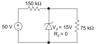
- In the voltage regulator shown below the power dissipation in the zener diode is—

-
View Hint View Answer Discuss in Forum
Since in the given problem RZ is zero. so, in order to calculate the power dissipation across the zener diode. We must calculate the current flowing in zener diode
Where, Vth = Thevenin equivalent voltage
Rth = Thevenin equivalent resistance
Vth = 75 = 50 . 1 75 + 150 3 = 50 V > VZ 3 Rth = 150 || 75 = 150 × 75 150 + 75
= 50 kΩiZ = Vth = 50/3 Rth + RL 50 kΩ
= 0.33 mA
Now PZ = VZ. iZ = 15 × 0.33 mA
= 0.5 mW
Hence alternative (D) is the correct choice.Correct Option: D
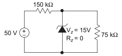
Since in the given problem RZ is zero. so, in order to calculate the power dissipation across the zener diode. We must calculate the current flowing in zener diode
Where, Vth = Thevenin equivalent voltage
Rth = Thevenin equivalent resistance
Vth = 75 = 50 . 1 75 + 150 3 = 50 V > VZ 3 Rth = 150 || 75 = 150 × 75 150 + 75
= 50 kΩiZ = Vth = 50/3 Rth + RL 50 kΩ
= 0.33 mA
Now PZ = VZ. iZ = 15 × 0.33 mA
= 0.5 mW
Hence alternative (D) is the correct choice.
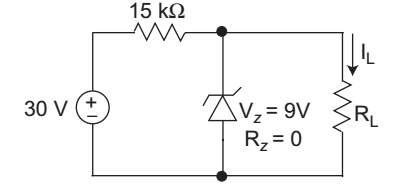
- In the voltage regular circuit shown below the maximum load current iL that can be drawn is—

-
View Hint View Answer Discuss in Forum
At regulated power supply i s = 30 – 9 = 1.4 mA 15 × 103
Therefore iL ≤ is = 1.4 mACorrect Option: A
At regulated power supply i s = 30 – 9 = 1.4 mA 15 × 103
Therefore iL ≤ is = 1.4 mA
- If P is passivation, Q is n-well implant, R is metallization and S is source/drain diffusion, then the order in which they are carried out in a standard n-well CMOS fabrication process is—
-
View Hint View Answer Discuss in Forum
NA
Correct Option: B
NA

