Physical electronics devices and ics miscellaneous
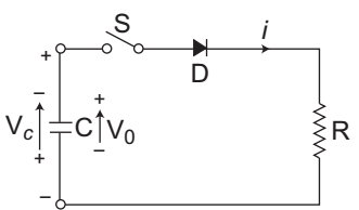
- In figure, capacitor C is initially charged with voltage V0 with upper plate positive. Switch S is closed at t = 0, At t = 0+, Vc and i are given by—
-
View Hint View Answer Discuss in Forum
The given circuit (i.e., fig)
From below figure, VC = – V0and i = V 0 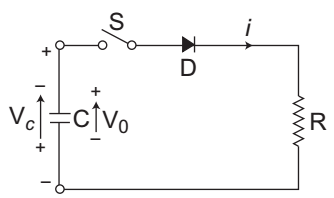
Correct Option: B
The given circuit (i.e., fig)
From below figure, VC = – V0and i = V 0 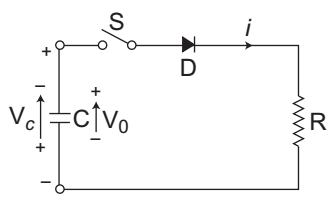
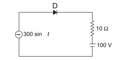
- In figure, PIV required for the diode is—
-
View Hint View Answer Discuss in Forum
The given circuit (i.e., fig-1)
The PIV (i.e., Peak Inverse Voltage) is the maximum voltage that appears across the diode when it is in nonconducting stage.
– PIV + 300 + 100 = 0
or PIV = 400 V
Hence alternative (D) is the correct choice.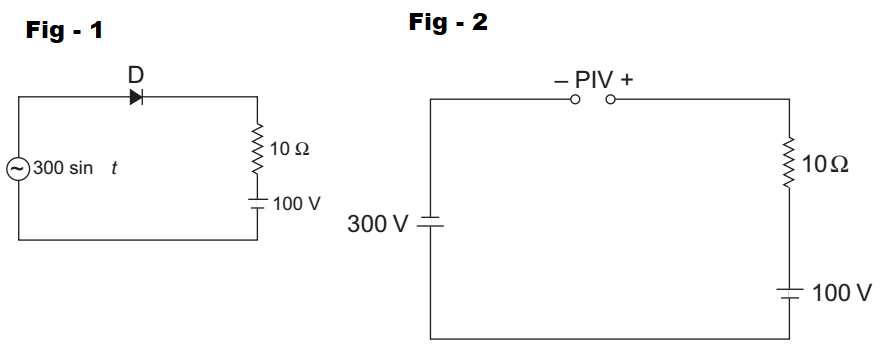
Correct Option: D
The given circuit (i.e., fig-1)
The PIV (i.e., Peak Inverse Voltage) is the maximum voltage that appears across the diode when it is in nonconducting stage.(i.e., fig-2)
– PIV + 300 + 100 = 0
or PIV = 400 V
Hence alternative (D) is the correct choice.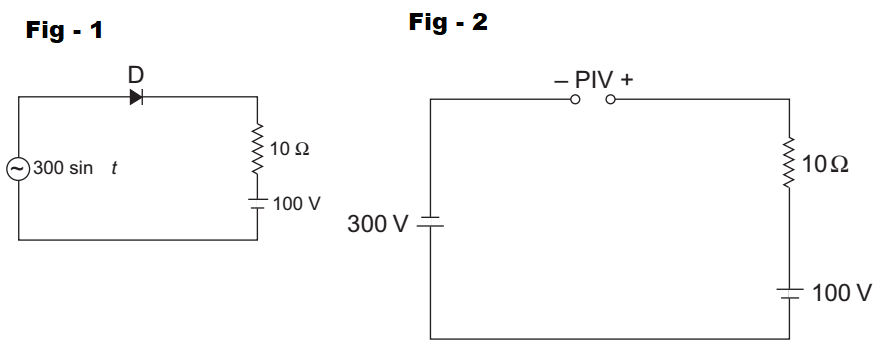
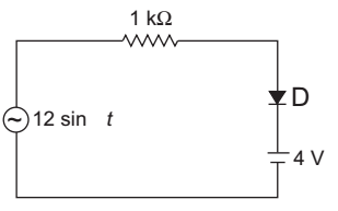
- The peak current through the resistor of circuit of figure, assuming the diodes to be ideal, is—
-
View Hint View Answer Discuss in Forum
The given circuit (i.e. fig - 1)
The equivalent circuit under peak voltage of 12V is given by (i.e. fig - 2)
I = (12 – 4) V 1 kΩ = 8 mA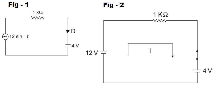
Correct Option: D
The given circuit (i.e. fig - 1)
The equivalent circuit under peak voltage of 12V is given by (i.e. fig - 2)
I = (12 – 4) V 1 kΩ = 8 mA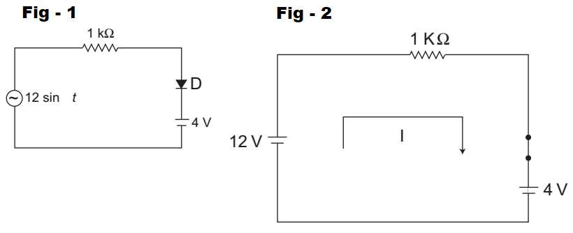
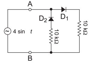
- A voltage V = 4 sin t is applied to the terminals A and B of the circuit shown in figure. The diodes are assumed to be ideal. The impedance offered by the circuit across the terminals A and B in kilo-ohms is—
-
View Hint View Answer Discuss in Forum
The given circuit (i.e., fig-1)
for the first half cycle equivalent circuit is given by (i.e., fig-2)
for the second half cycle the equivalent circuit is given by (i.e., fig-3)
Hence alternative (C) is the correct choice.
Correct Option: C
The given circuit (i.e., fig-1)
for the first half cycle equivalent circuit is given by (i.e., fig-2)
for the second half cycle the equivalent circuit is given by (i.e., fig-3)
Hence alternative (C) is the correct choice.
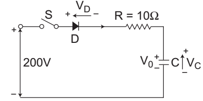
- In figure, capacitor C is charged to V0 = 50 V with upper plate positive. Switch S is closed at t = 0. Current through the circuit at t = 0 and final voltage across C are respectively—
-
View Hint View Answer Discuss in Forum
The given circuit
at t = 0 the equivalent circuit becomesI = (200 – 50) V = 15 A 10Ω
And, the final voltage across C means at steady state capacitors becomes open circuited as shown below:
VC(∞) = 200V
Hence alternative (A) is the correct choice.
Correct Option: A
The given circuit
at t = 0 the equivalent circuit becomesI = (200 – 50) V = 15 A 10Ω
And, the final voltage across C means at steady state capacitors becomes open circuited as shown below:
VC(∞) = 200V
Hence alternative (A) is the correct choice.

