Physical electronics devices and ics miscellaneous
- In a forward biased photodiode with increase in incident light intensity, the diode current—
-
View Hint View Answer Discuss in Forum
In a forward biased photodiode with increase in incident light intensity, the diode current decreases.
Description: Figure given below shows the optical generation of carriers in a forward biased p-n junction photodiode
The diode current is given by relationI=Ith 
ηV 
- Iop ....(A) eKT – 1
and Iop = q Agop (Lp + Ln + W)
where, gop = optical generation rate
Thus from equation (A) it is clear that increase in incident light intensity the optical generation rate will increase and the net diode current will decrease.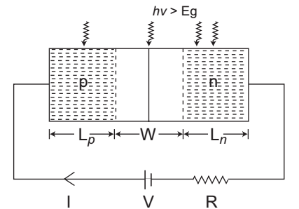
Correct Option: C
In a forward biased photodiode with increase in incident light intensity, the diode current decreases.
Description: Figure given below shows the optical generation of carriers in a forward biased p-n junction photodiode
The diode current is given by relationI=Ith 
ηV 
- Iop ....(A) eKT – 1
and Iop = q Agop (Lp + Ln + W)
where, gop = optical generation rate
Thus from equation (A) it is clear that increase in incident light intensity the optical generation rate will increase and the net diode current will decrease.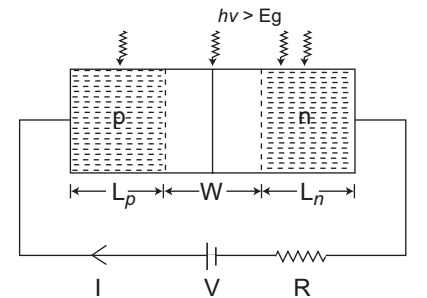
- Consider the following circuit.
Zener diode has zener voltage VZ = 16 V at a minimum iZ of 15 mA. If Vb = 24 ± 3V and RL varies from 250 Ω to 2 kΩ, find the value of RS to maintain regulation—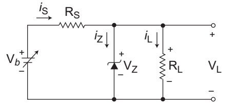
-
View Hint View Answer Discuss in Forum
The given circuit (i.e., fig)
Given, VZ = 16V, IZ(min) = 15 mA
Vb = 24 ± 3V gives Vb(min)
= 21V & Vb(max) = 27V
RL varies from 250Ω to 2KΩ
RS =?IL(min) = VZ = 16V = 8 mA 2KΩ 2KΩ IL(max) = VZ = 16V = 64 mA 250Ω 250Ω
The minimum value of RS to maintain the regulation is given by expressionRS ≤ Vb(min) – VZ IZK + IL(max) or RS ≤ 21 V – 16 V 15 mA + 64 mA or RS ≤ 5 V 79 mA
or RS ≤ 63·29Ω
Hence alternative (C) is the correct choice.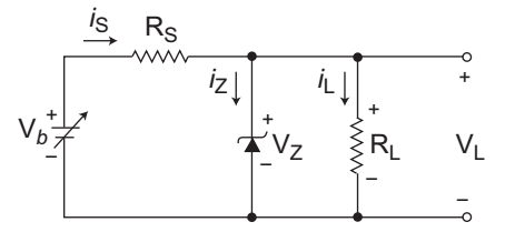
Correct Option: C
The given circuit (i.e., fig)
Given, VZ = 16V, IZ(min) = 15 mA
Vb = 24 ± 3V gives Vb(min)
= 21V & Vb(max) = 27V
RL varies from 250Ω to 2KΩ
RS =?IL(min) = VZ = 16V = 8 mA 2KΩ 2KΩ IL(max) = VZ = 16V = 64 mA 250Ω 250Ω
The minimum value of RS to maintain the regulation is given by expressionRS ≤ Vb(min) – VZ IZK + IL(max) or RS ≤ 21 V – 16 V 15 mA + 64 mA or RS ≤ 5 V 79 mA
or RS ≤ 63·29Ω
Hence alternative (C) is the correct choice.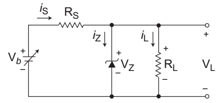
- In the following limiter circuit, an input voltage Vi = 10 sin 100 πt is applied. Assume that the diode drop is 0·7 V when it is forward biased. The Zener breakdown voltage is 6·8 V.
The maximum and minimum values of the output voltage respectively are—
-
View Hint View Answer Discuss in Forum
The given circuit (i.e., fig - 1)
Given VD1 = VD2 = 0·7V and VZ = 6·8V
For first half cycle equivalent circuit of the given circuit is shown below (i.e., fig - 2)
From above circuit V0 = 0·7 + 6·8 = 7·5V
For second half cycle the equivalent circuit is shown below: (i.e., fig - 3)
From figure, V0 = – 0·7V
Therefore maximum value of output voltage is 7·5V and minimum value of output voltage is – 0·7V.
Hence alternative (C) is the correct choice
Correct Option: C
The given circuit (i.e., fig - 1)
Given VD1 = VD2 = 0·7V and VZ = 6·8V
For first half cycle equivalent circuit of the given circuit is shown below (i.e., fig - 2)
From above circuit V0 = 0·7 + 6·8 = 7·5V
For second half cycle the equivalent circuit is shown below: (i.e., fig - 3)
From figure, V0 = – 0·7V
Therefore maximum value of output voltage is 7·5V and minimum value of output voltage is – 0·7V.
Hence alternative (C) is the correct choice
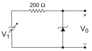
- For the Zener diode shown in the figure, the Zener voltage at knee is 7 V, the knee current is negligible and the Zener dynamic resistance is 10 Ω. If the input voltage (Vi) range is from 10 to 16 V, the output voltage (V0) ranges from—
-
View Hint View Answer Discuss in Forum
The given figure (i.e., fig - 1)
Given, VZ = 7V, rZ = 10Ω
Vi range 10 to 16 V
V0 range =?
The given circuit can be modified as shown below (i.e., fig - 2)
When, Vi = 10V i.e., Vi(min)Then, I = 10 – 7 = 3 A 210 210
and V0(min) = I × 10 + VZ= 3 × 10 + 7 = 7·14V 210
When, Vi = 16V i.e., Vi(max)Then, I = 16 – 7 = 9 A 210 210 and V0(max) = I × 10 + VZ = 9 × 10 + 7 210
= 7·428 ≈ 7·43V
Hence alternative (C) is the correct choice.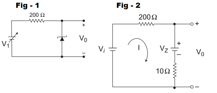
Correct Option: C
The given figure (i.e., fig - 1)
Given, VZ = 7V, rZ = 10Ω
Vi range 10 to 16 V
V0 range =?
The given circuit can be modified as shown below (i.e., fig - 2)
When, Vi = 10V i.e., Vi(min)Then, I = 10 – 7 = 3 A 210 210
and V0(min) = I × 10 + VZ= 3 × 10 + 7 = 7·14V 210
When, Vi = 16V i.e., Vi(max)Then, I = 16 – 7 = 9 A 210 210 and V0(max) = I × 10 + VZ = 9 × 10 + 7 210
= 7·428 ≈ 7·43V
Hence alternative (C) is the correct choice.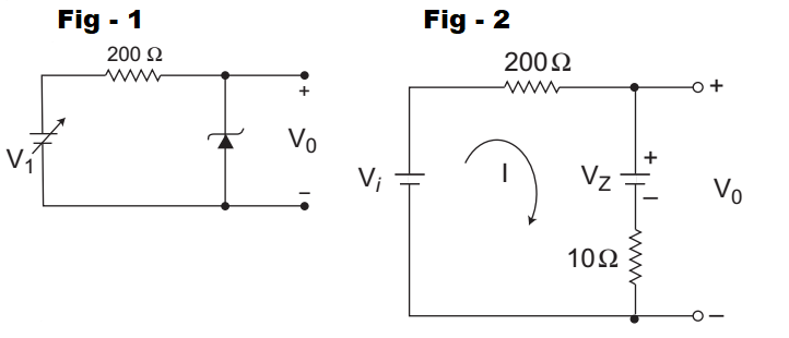
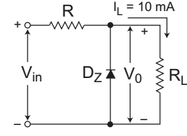
- A Zener diode regulator shown in the figure given below is to be designed to meet the following specifications—
IL = 10 mA, V0 = 10 V, Vin varies from 30 V to 50 V. The zener diode has VZ = 10 V and IZK (knee current) = 1 mA. For satisfactory operation, which one of the following is correct?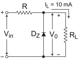
-
View Hint View Answer Discuss in Forum
The given circuit (i.e., fig)
Given, V0 = VZ = 10V
IL = 10 mA
IZK (Knee current) = 1 mA
30V ≤ Vi ≤ 50V
From figure IR(min) = Vi(min) – VZ R
R ≤ Vi(min) – VZ IZK + IL
or R ≤ 30 – 10 1 mA + 10 mA
or R ≤ 1818Ω
Hence alternative (A) is the correct choice.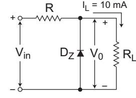
Correct Option: A
The given circuit (i.e., fig)
Given, V0 = VZ = 10V
IL = 10 mA
IZK (Knee current) = 1 mA
30V ≤ Vi ≤ 50V
From figure IR(min) = Vi(min) – VZ R
R ≤ Vi(min) – VZ IZK + IL
or R ≤ 30 – 10 1 mA + 10 mA
or R ≤ 1818Ω
Hence alternative (A) is the correct choice.