Physical electronics devices and ics miscellaneous
- In zener and avalanche breakdown diodes, current flow is due to—
-
View Hint View Answer Discuss in Forum
In zener and avalanche breakdown diodes, current flow is due to majority carriers.
Correct Option: B
In zener and avalanche breakdown diodes, current flow is due to majority carriers.
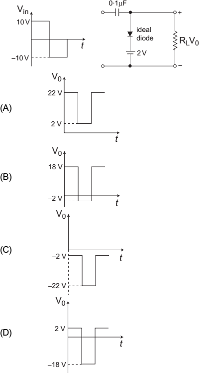
- Select the correct output (V0) wave shape for a given input (Vi) in clamping network shown below—

-
View Hint View Answer Discuss in Forum
The given circuit (i.e., fig -1)
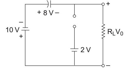
Equivalent circuit for the first half cycle is given below (i.e., fig -2)
V0 = 2V and VC = 8V with mentioned polarity Now, the equivalent circuit for second half cycle is shown below (i.e., fig -3)
V0 + 8 + 10 = 0
or V0 = – 18V
Hence alternative (D) is the correct choice.
Correct Option: D
The given circuit (i.e., fig -1)
Equivalent circuit for the first half cycle is given below (i.e., fig -2)
V0 = 2V and VC = 8V with mentioned polarity Now, the equivalent circuit for second half cycle is shown below (i.e., fig -3)
V0 + 8 + 10 = 0
or V0 = – 18V
Hence alternative (D) is the correct choice.
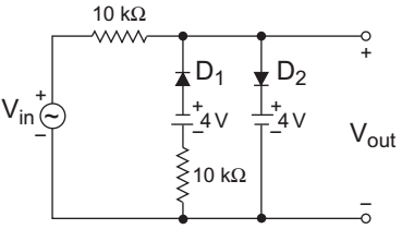
- A voltage signal 10 sin t is applied to the circuit with ideal diodes, as shown in figure. The maximum and minimum values of the output waveform Vout of the circuit are respectively—

-
View Hint View Answer Discuss in Forum
The given circuit (i.e., fig-1)
For first half cycle the diode D2 will conduct while diode D1 will not conduct. Equivalent circuit for this case is shown below: (i.e., fig-2)
For the second half cycle diode D1 will conduct while diode D1 will not conduct. Equivalent circuit for this case is shown below: (i.e., fig-3)
From above figure
– 10 KI – 4 – 10 KI + 10 = 0or I = 6 mA 20 V0 = – 4 – 10 × 6 = – 4 – 3 20
= – 7V = V0 (min)
Hence alternative (D) is the correct choice.
Correct Option: D
The given circuit (i.e., fig-1)
For first half cycle the diode D2 will conduct while diode D1 will not conduct. Equivalent circuit for this case is shown below: (i.e., fig-2)
For the second half cycle diode D1 will conduct while diode D1 will not conduct. Equivalent circuit for this case is shown below: (i.e., fig-3)
From above figure
– 10 KI – 4 – 10 KI + 10 = 0or I = 6 mA 20 V0 = – 4 – 10 × 6 = – 4 – 3 20
= – 7V = V0 (min)
Hence alternative (D) is the correct choice.
- At high frequencies, ordinary diodes does not work properly because of—
-
View Hint View Answer Discuss in Forum
At high frequencies, ordinary diodes does not work properly because of charge storage.
Correct Option: D
At high frequencies, ordinary diodes does not work properly because of charge storage.
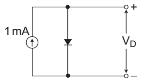
- In figure, a silicon diode is carrying a constant current of 1 mA. When the temperature of the diode is 20°C, VD is found to be 700 mV. If the temperature raises to 40°C, VD becomes approximately equal to—

-
View Hint View Answer Discuss in Forum
We know that on increasing 1°C of temperature the cut-in-voltage Vr of the diode is approximately decreases by – 2·5 mV/°C.
So, net increase in temperature = (40 – 20) = 20°C
decrease in cut-in-voltage by = 700 mV – 20 × 2·5 mV = 650 mV (approximately)Correct Option: B
We know that on increasing 1°C of temperature the cut-in-voltage Vr of the diode is approximately decreases by – 2·5 mV/°C.
So, net increase in temperature = (40 – 20) = 20°C
decrease in cut-in-voltage by = 700 mV – 20 × 2·5 mV = 650 mV (approximately)

