Analog electronics circuits miscellaneous
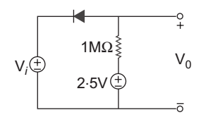
- A symmetrical 5 kHz square wave whose output varies between + 10 V and – 10 V is impressed upon the clipping circuit shown below. If diode has rf = 0 and rr = 2 MΩ and Vr = 0, the output waveform is:
-
View Hint View Answer Discuss in Forum
The diode will conduct when νi < 2.5 V → Vo = Vi diode will not conduct when νi > 2.5 i.e., diode is open with 2 MΩ resistance.
νo = 2.5 V + ( νi - 2.5 ) × 1 1 + 2 νo = 2.5 V + νi - 2.5 3 νo = 2.5 V + 10 - 2.5 = 5 V ( when vi = 10V) 3
when vi < 2.5 V, Vo = Vi = – 10V which is given in option (B)
Hence alternative (B) is the correct choice.
Correct Option: B
The diode will conduct when νi < 2.5 V → Vo = Vi diode will not conduct when νi > 2.5 i.e., diode is open with 2 MΩ resistance.
νo = 2.5 V + ( νi - 2.5 ) × 1 1 + 2 νo = 2.5 V + νi - 2.5 3 νo = 2.5 V + 10 - 2.5 = 5 V ( when vi = 10V) 3
when vi < 2.5 V, Vo = Vi = – 10V which is given in option (B)
Hence alternative (B) is the correct choice.
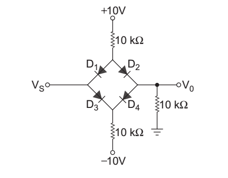
- For the circuit shown below each diode has Vγ = 0.7 V. The V0 for – 10 ≤ Vs < 10 V is:
-
View Hint View Answer Discuss in Forum
For Vs > 0, when D1 is OFF, current will flow through diode D2 and is given by:
i = 10 - 0.7 = 0.465 mA 10 + 10
νo = 10 × i = 10 × 0.465 = 4.65 V
it means we conclude that
νo = νs for 0 < νs < 4.65 V
for negative values of νs, we get the same output but in negaive magnitude.
Hence alternative (D) is the correct choice.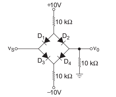
Correct Option: D
For Vs > 0, when D1 is OFF, current will flow through diode D2 and is given by:
i = 10 - 0.7 = 0.465 mA 10 + 10
νo = 10 × i = 10 × 0.465 = 4.65 V
it means we conclude that
νo = νs for 0 < νs < 4.65 V
for negative values of νs, we get the same output but in negaive magnitude.
Hence alternative (D) is the correct choice.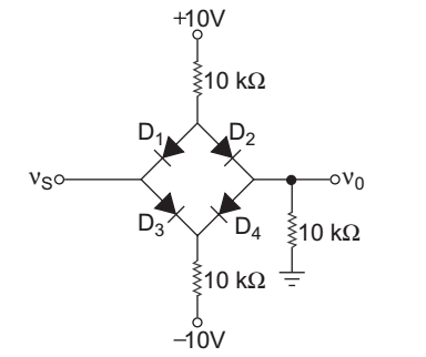
- For the circuit given below the cut-in voltage of diode is
Vγ = 0.7 V. The plot of V0 versus Vi is:
-
View Hint View Answer Discuss in Forum
ν0 = νi + 15. 1 = νi + 5 (1 + 2)
Cut-in-voltage of the diode, νf = 0.7 V
for voltage νi ≤ 5.7 the diode will not conduct and ν0 = νi
Let general case when diode is on, then KCL at point A.ν0 - νi + ν0 + ν0 - 15 = 0 1k 1k 2k V0 
1 + 1 + 1 
= Vi + 15 2 2 V0 
5 
= Vi + 15 2 2
ν0 = 0·4vi + 3
Hence alternative (C) is the most closest choice.
Correct Option: C
ν0 = νi + 15. 1 = νi + 5 (1 + 2)
Cut-in-voltage of the diode, νf = 0.7 V
for voltage νi ≤ 5.7 the diode will not conduct and ν0 = νi
Let general case when diode is on, then KCL at point A.ν0 - νi + ν0 + ν0 - 15 = 0 1k 1k 2k V0 
1 + 1 + 1 
= Vi + 15 2 2 V0 
5 
= Vi + 15 2 2
ν0 = 0·4vi + 3
Hence alternative (C) is the most closest choice.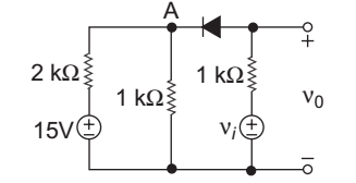
- Which of the following pairs is/are correctly matched?
Waveform Circuit and Input Signal 1. Triangular wave Integrating circuit and square wave 2. Impulsive wave Differentiating circuit and step signal. 3. Sawtooth wave Differentiating circuit and triangular wave.
Select the correct answer using the codes given below:
-
View Hint View Answer Discuss in Forum
(i) Square wave passes through a integrating circuit → Triangular wave.
(ii) Step input passes through a differentiating circuit → Impulse wave.
(iii) Triangular wave passes through a differentiating circuit → Square wave
Since (i) and (ii) is only correct.
Hence alternative (B) is the correct choice.Correct Option: B
(i) Square wave passes through a integrating circuit → Triangular wave.
(ii) Step input passes through a differentiating circuit → Impulse wave.
(iii) Triangular wave passes through a differentiating circuit → Square wave
Since (i) and (ii) is only correct.
Hence alternative (B) is the correct choice.
- When a square wave pulse fed to the input of the circuit shown in the given figure then VC, the voltage across C will the waveform:

-
View Hint View Answer Discuss in Forum
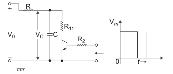
From given fig. we conclude that output coming from the C.E. amplifier is connected with low pass filter which acts as a integrator, due to C.E. amplifier the phase of the triangular wave become reverse.
Hence alternative (D) is the correct choice.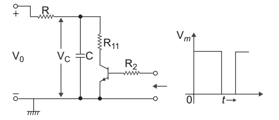
Correct Option: D
From given fig. we conclude that output coming from the C.E. amplifier is connected with low pass filter which acts as a integrator, due to C.E. amplifier the phase of the triangular wave become reverse.
Hence alternative (D) is the correct choice.