Analog electronics circuits miscellaneous
Direction: Consider the circuit Assume diodes are ideal.

- 50. If V1 = 10 V and V2 = 5 V, then output voltage V0 is:
-
View Hint View Answer Discuss in Forum
In such type of circuit arrangement at first sight it might not be obvious whether none, one or both diodes are conduct. In such type of circuit arrangement we should apply a plausible assumption, proceed with the analysis, and then check whether we end up with a consistent solution.
Assume D1 is ON and D2 is OFFV0 = Vi × 9 = 10. 9 = 9 V 1 + 9 10
Check AssumptionID1 = V1 – V0 = 10 – 9 = 1 mA > 0 therefore D1 is ON 1 kΩ 1
i.e. assumption is correct.
At the same time
VD2 = V2 – V0 = 5 – 9 = – 4 < 0 therefore, D2 OFF
Hence alternative (A) is the correct choice.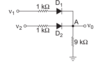
Correct Option: A
In such type of circuit arrangement at first sight it might not be obvious whether none, one or both diodes are conduct. In such type of circuit arrangement we should apply a plausible assumption, proceed with the analysis, and then check whether we end up with a consistent solution.
Assume D1 is ON and D2 is OFFV0 = Vi × 9 = 10. 9 = 9 V 1 + 9 10
Check AssumptionID1 = V1 – V0 = 10 – 9 = 1 mA > 0 therefore D1 is ON 1 kΩ 1
i.e. assumption is correct.
At the same time
VD2 = V2 – V0 = 5 – 9 = – 4 < 0 therefore, D2 OFF
Hence alternative (A) is the correct choice.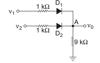
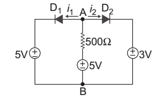
- In the circuit shown below D1 and D2 are ideal diodes. The current i1 and i 2 are:
-
View Hint View Answer Discuss in Forum
From given figure let the current flowing through the terminal A and B is Ix (from B to A) and VAB < 5 V (always) Due to this Diode D2 remain in the OFF therefore i1 = 0.
And Ix = Iz = 5 – 3 = 4 mA 500
Hence alternative (A) is the correct choice.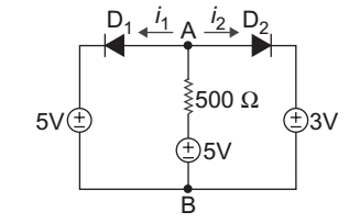
Correct Option: A
From given figure let the current flowing through the terminal A and B is Ix (from B to A) and VAB < 5 V (always) Due to this Diode D2 remain in the OFF therefore i1 = 0.
And Ix = Iz = 5 – 3 = 4 mA 500
Hence alternative (A) is the correct choice.
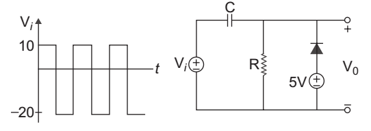
- For the circuit shown below the input voltage Vi is as shown in fig. Assume the RC time constant large and cutin voltage Vr = 0. The output voltage V0 is:
-
View Hint View Answer Discuss in Forum
For input νi ≤ 5 V diode
will conduct and capacitor will charge to Vc – 5 – 20 ÷ Vc = 25 volt
and Vo = + 5 V.
However if Vi ≥ 5 V the diode will not conduct
and V0max = Vc + Vi = 25 + 10 = 35 V.
Hence alternative (A) is the correct choice.
Correct Option: A
For input νi ≤ 5 V diode
will conduct and capacitor will charge to Vc – 5 – 20 ÷ Vc = 25 volt
and Vo = + 5 V.
However if Vi ≥ 5 V the diode will not conduct
and V0max = Vc + Vi = 25 + 10 = 35 V.
Hence alternative (A) is the correct choice.
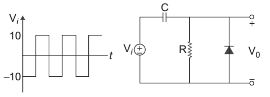
- For the circuit shown below the input voltage Vi is as shown below. Assume the RC time constant large and cut-in voltage of diode Vr = 0. The output voltage V0 is:
-
View Hint View Answer Discuss in Forum
In negative cycle diode will be ON and capacitor will be charged, at this cycle we get 0 V output and capacitor will charge to 10 V. In positive cycle diode will be off and
νo = νc + νi = 10 + 10 = 20 V
the given circuit acts as a positive clamper
Hence alternative (B) is the correct choice.
Correct Option: B
In negative cycle diode will be ON and capacitor will be charged, at this cycle we get 0 V output and capacitor will charge to 10 V. In positive cycle diode will be off and
νo = νc + νi = 10 + 10 = 20 V
the given circuit acts as a positive clamper
Hence alternative (B) is the correct choice.
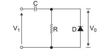
- The circuit shown below is a:

-
View Hint View Answer Discuss in Forum
Since during the negative half cycle the diode becomes ON and we get zero output and capacitor charged with peak voltage of input signal. That’s why it is called positive clamper.
Correct Option: A
Since during the negative half cycle the diode becomes ON and we get zero output and capacitor charged with peak voltage of input signal. That’s why it is called positive clamper.


