Analog electronics circuits miscellaneous
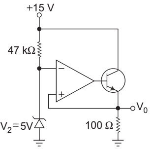
- In the circuit shown below the op-amp is ideal. If βF = 60, then the total current supplied by the 15 V source is:
-
View Hint View Answer Discuss in Forum
Given
V+ = 5 V
V– = VE = 5 V (due to virtual ground)Ie = 5 = 50 mA 100
since ideal op-amp draws no current, soIz = 15 – V+ , Ie = Ib + Ic 47 kΩ = 15 – 5 , or Ic = Ie – Ib 47 kΩ
= 0·213 mA , or βIb + Ib = IeIe = Vo , or Ib = Ie ⇒ Ic = β·Ie 100 1 + β (1 + β)
= 50 mA
The total current supplied by the 15 V source= Iz + Ic = Iz + β·Ie (1 + β) = 
0·213 + 60·(50) 
mA = 49.39 mA 61
Hence alternative (C) is the correct choice.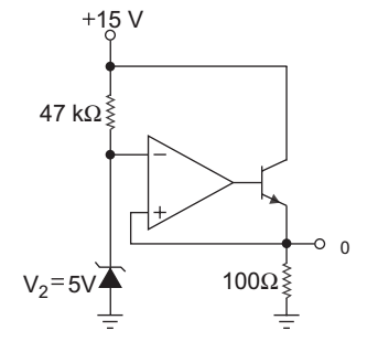
Correct Option: C
Given
V+ = 5 V
V– = VE = 5 V (due to virtual ground)Ie = 5 = 50 mA 100
since ideal op-amp draws no current, soIz = 15 – V+ , Ie = Ib + Ic 47 kΩ = 15 – 5 , or Ic = Ie – Ib 47 kΩ
= 0·213 mA , or βIb + Ib = IeIe = Vo , or Ib = Ie ⇒ Ic = β·Ie 100 1 + β (1 + β)
= 50 mA
The total current supplied by the 15 V source= Iz + Ic = Iz + β·Ie (1 + β) = 
0·213 + 60·(50) 
mA = 49.39 mA 61
Hence alternative (C) is the correct choice.
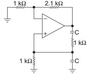
- The value of C required for sinusoidal oscillation of frequency 1 kHz in the circuit shown below:
-
View Hint View Answer Discuss in Forum
The given circuit represents the wien bridge oscillator.
The ratio R2 must be greater than 2 for oscillation to start. R1 Since here ratio R2 = 2.1 = 2.1 > 2 R1 1
so there will oscillation and frequency of oscillationf = 1 2πRC 1 × 103 = 1 2π × 1 × 103 × C or C = 1 × 10⁶ F 2π or C = 1 µF 2π Correct Option: A
The given circuit represents the wien bridge oscillator.
The ratio R2 must be greater than 2 for oscillation to start. R1 Since here ratio R2 = 2.1 = 2.1 > 2 R1 1
so there will oscillation and frequency of oscillationf = 1 2πRC 1 × 103 = 1 2π × 1 × 103 × C or C = 1 × 10⁶ F 2π or C = 1 µF 2π
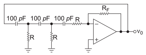
- The phase shift oscillator shown below operate at f = 80 kHz. The value of resistance RF is:
-
View Hint View Answer Discuss in Forum
Frequency of oscillation in the phase shift oscillator,
f = 1 2π 6 RC 80 × 103 = 1 2π 6 × R × 100 × 10–12 or R = 106 8 × 2π × 6
or R = 8.12 kΩand, gain = RF = 29 R
or RF = 29 R = 29 × 8.12 kΩ = 235.65 kΩ
or RF 236 kΩCorrect Option: B
Frequency of oscillation in the phase shift oscillator,
f = 1 2π 6 RC 80 × 103 = 1 2π 6 × R × 100 × 10–12 or R = 106 8 × 2π × 6
or R = 8.12 kΩand, gain = RF = 29 R
or RF = 29 R = 29 × 8.12 kΩ = 235.65 kΩ
or RF 236 kΩ
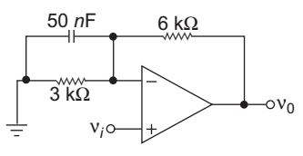
- In the filter circuit shown below the 3 dB cut-off frequency is:
-
View Hint View Answer Discuss in Forum
f3dB = 1 2πRC
Here R = R1 || R2 where R1 = 3 kΩ
= 3 || 6 = 2 k R2 = 6 kΩf3dB = 1 = 1.59 kHz 2π × 2 × 103 × 50 × 10–9 Correct Option: B
f3dB = 1 2πRC
Here R = R1 || R2 where R1 = 3 kΩ
= 3 || 6 = 2 k R2 = 6 kΩf3dB = 1 = 1.59 kHz 2π × 2 × 103 × 50 × 10–9
- A 50 kHz square wave is to be amplified by an op-amp to have an output voltage swing ± 10 V. Two op-amp are available A has slew rate of 0.5 V/µs and B has slew rate of 13 V/µs. Then correct answer is:
-
View Hint View Answer Discuss in Forum
Given that output voltage swing = ± 10 V and input wave is square wave with 50 kHz
Slew rate for op-amp A = 0.5 V/µs.
Slew rate for op-amp B = 13 V/µs.
Maximum output voltage after passing a square wave can be calculated as first
Check for op-amp ASlew rate of op-amp A = 2πf·Vm 106
0.5 × 106 = 2π × 50 × 103. Vmor Vm = 0·5 × 103 314
Vm = 1.59 V
Since this voltage is less than the output voltage swing i.e. ± 10 V.
Therefore op-amp A is not suitable for amplified a 50 kHz square wave.
Now check for op-amp BVm = Slew rate × 106 2πf = 13 × 106 = 41.4 V 2 × 3·14 × 50 × 103
Since this voltage is higher than the output voltage swing i.e. ± 10 V.
Therefore op-amp B is suitable for amplifying 50 kHz square wave.
Hence alternative (C) is the correct choice.Correct Option: C
Given that output voltage swing = ± 10 V and input wave is square wave with 50 kHz
Slew rate for op-amp A = 0.5 V/µs.
Slew rate for op-amp B = 13 V/µs.
Maximum output voltage after passing a square wave can be calculated as first
Check for op-amp ASlew rate of op-amp A = 2πf·Vm 106
0.5 × 106 = 2π × 50 × 103. Vmor Vm = 0·5 × 103 314
Vm = 1.59 V
Since this voltage is less than the output voltage swing i.e. ± 10 V.
Therefore op-amp A is not suitable for amplified a 50 kHz square wave.
Now check for op-amp BVm = Slew rate × 106 2πf = 13 × 106 = 41.4 V 2 × 3·14 × 50 × 103
Since this voltage is higher than the output voltage swing i.e. ± 10 V.
Therefore op-amp B is suitable for amplifying 50 kHz square wave.
Hence alternative (C) is the correct choice.

