Network Elements and the Concept of Circuit
- Reciprocity theorem is valid for—
-
View Hint View Answer Discuss in Forum
Reciprocity theorem is valid for all linear, passive and bilateral networks.
Correct Option: D
Reciprocity theorem is valid for all linear, passive and bilateral networks.
- An ideal voltage source and ideal current source are connected in parallel this circuit has—
-
View Hint View Answer Discuss in Forum
NA
Correct Option: B
NA
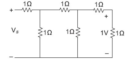
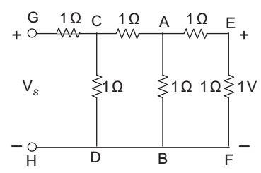
- For the circuit shown in figure, the voltage Vs will be
-
View Hint View Answer Discuss in Forum
Current in branch EF = 1 1 amp 1 Current in Branch AB = VAB = 2 = 2 amp 1Ω 1
Current in branch CA = 1 + 2 = 3 amp.Current in CD = VCD = ACA + VAB 1 1 = 3 × 1 + 2 × 1 1
= 5amp
Current in branch GC = 5 + 3 = 8 amp
Now, Vs = VGC + VCD
= 1 × 8 + 1 × 5
= 13 V

Correct Option: D
Current in branch EF = 1 1 amp 1 Current in Branch AB = VAB = 2 = 2 amp 1Ω 1
Current in branch CA = 1 + 2 = 3 amp.Current in CD = VCD = ACA + VAB 1 1 = 3 × 1 + 2 × 1 1
= 5amp
Current in branch GC = 5 + 3 = 8 amp
Now, Vs = VGC + VCD
= 1 × 8 + 1 × 5
= 13 V
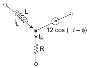
- The network shown, if iR = (4 e— 3t + 5 e— 4t) amp and i L (0) = 15 amp, then at t = 0 φ would be equal to—
-
View Hint View Answer Discuss in Forum
From given figure
IL = IR + I2 cos (t – φ)
15 = (4e–3t + 5e–4t) + 12 cos (t – φ)
at t = 0
15 = 4 + 5 + 12 cos (–φ)
or 15 – 9 = 12 cos φ
or 6 = 12 cos φor cos φ = 1 2 or φ = π 3

Correct Option: B
From given figure
IL = IR + I2 cos (t – φ)
15 = (4e–3t + 5e–4t) + 12 cos (t – φ)
at t = 0
15 = 4 + 5 + 12 cos (–φ)
or 15 – 9 = 12 cos φ
or 6 = 12 cos φor cos φ = 1 2 or φ = π 3

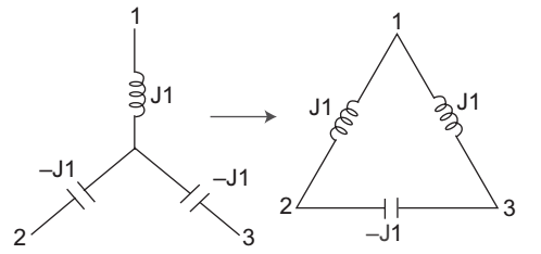
- Which of the following networks in the equivalent of the circuit shown in figure?

-
View Hint View Answer Discuss in Forum
This can be solved by using Star to Delta transformation.
R12 = R1R2 + R2R3 + R3R1 R3 = J1 × -J1 + (-J1) + (-J1)× (J1) -J1 = J2 + J2- J2 = +J -J R23 = R1R2 + R2R3 + R3R1 = -J2 = -J R1 J R31 = R1R2 + R2R3 + R3R1 = -J2 = J R2 J 
Correct Option: A
This can be solved by using Star to Delta transformation.
R12 = R1R2 + R2R3 + R3R1 R3 = J1 × -J1 + (-J1) + (-J1)× (J1) -J1 = J2 + J2- J2 = +J -J R23 = R1R2 + R2R3 + R3R1 = -J2 = -J R1 J R31 = R1R2 + R2R3 + R3R1 = -J2 = J R2 J