Network Elements and the Concept of Circuit
- For the circuit shown below. Power is delivered by—

-
View Hint View Answer Discuss in Forum
The given circuit → Circuit correction
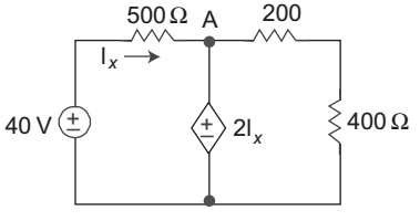
KCL at node A.VA – 40 + VA – 0 = 0 ...................(i) 500 600
VA = 2ix ........................(ii)
Again from given circuitix = 40 – VA 500 VA 
1 + 1 
= 40 500 600 500 or VA 1100 = 40 500 × 600 500 or VA = 40 × 600 1100
or VA = 21.82 Vlx = VA = 21.82 = 10.90 A 2 2
Since lx is positive. So power is delivered by independent source i.e. Pdelivered = 40 × lx
or = 40 × 10.90 = 436 WCorrect Option: D
The given circuit → Circuit correction
KCL at node A.VA – 40 + VA – 0 = 0 ...................(i) 500 600
VA = 2ix ........................(ii)
Again from given circuitix = 40 – VA 500 VA 1 + 1 = 40 500 600 500 or VA 1100 = 40 500 × 600 500 or VA = 40 × 600 1100
or VA = 21.82 Vlx = VA = 21.82 = 10.90 A 2 2
Since lx is positive. So power is delivered by independent source i.e. Pdelivered = 40 × lx
or = 40 × 10.90 = 436 W
- For the circuit shown below. The dependent source—

-
View Hint View Answer Discuss in Forum
Given, lx = 5A
Voltage at dependent source terminal is
= – 2 ix
= – 2 × 5 = – 10V
P = V × ix
or P = 10 × 5 = 50 W
Since current is entering in the independent source. It means power is absorbed by the dependent source.Correct Option: B
Given, lx = 5A
Voltage at dependent source terminal is
= – 2 ix
= – 2 × 5 = – 10V
P = V × ix
or P = 10 × 5 = 50 W
Since current is entering in the independent source. It means power is absorbed by the dependent source.
- Calculate Z parameter for the circuit given below—

-
View Hint View Answer Discuss in Forum
The given circuit can be redrawn as shown below

Applying KVL in loop 1.
V1 = 2 (I1 – I) ................(i)
KVL in loop 2
– 3I + 2V1 – (I2 + I) 4 + 2 (I1 – I) = 0
or 9I = 2V1 – 4 I2 + 2I1or I = 2V1 + 2I1 – 4I2 ...................(ii) 9
From equations (i) and (ii)V1 = 2I1 – 2 (2V1 + 2I1 – 4I2) 9 or 9 V1 
1 + 4 
= 18I1 – 4I1 + 8I2 9
or 13V1 = 14 I1 + 8I2or V1 = 14 I1 + 8 I2 ............(iii) 13 13
We know that
V1 = Z11 I1 + Z12 I2 ..........(iv)
(for Z-parameter)
Comparing equations (iii) and (iv), we getZ11 = 14 , Z12 = 8 13 13
Applying KVL in loop 3.
V2 = 4 (I2 + I)or V2 = 4 I2 + 4 2V1 + 2I1 – 4I2 9
[from equation (ii)]or V2 = 4 I2 + 8 V1 + 8 I1 –16 I2 9 9 9 or V2 = 4 I2 + 8 14 I1 + 8 I2 + 8 I1 –16 I2 9 13 13 9 9 or V2 = I2 4 + 64 – 16 + I1 112 + 8 117 9 117 9 or V2 = I2 (466 + 64 – 208) + I1 112 + 104 117 117 or V2 = 314 I2 + 216 I1 .......(v) 117 117
We know that
V2 = Z21 I1 + Z22 I2 (for Z-parameters) ..............(vi)
Comparing equations (v) and (vi), we getZ21 = 216 , Z22 = 314 117 117
Hence alternative (A) is the correct choice.Correct Option: B
The given circuit can be redrawn as shown below
Applying KVL in loop 1.
V1 = 2 (I1 – I) ................(i)
KVL in loop 2
– 3I + 2V1 – (I2 + I) 4 + 2 (I1 – I) = 0
or 9I = 2V1 – 4 I2 + 2I1or I = 2V1 + 2I1 – 4I2 ...................(ii) 9
From equations (i) and (ii)V1 = 2I1 – 2 (2V1 + 2I1 – 4I2) 9 or 9 V1 1 + 4 = 18I1 – 4I1 + 8I2 9
or 13V1 = 14 I1 + 8I2or V1 = 14 I1 + 8 I2 ............(iii) 13 13
We know that
V1 = Z11 I1 + Z12 I2 ..........(iv)
(for Z-parameter)
Comparing equations (iii) and (iv), we getZ11 = 14 , Z12 = 8 13 13
Applying KVL in loop 3.
V2 = 4 (I2 + I)or V2 = 4 I2 + 4 2V1 + 2I1 – 4I2 9
[from equation (ii)]or V2 = 4 I2 + 8 V1 + 8 I1 –16 I2 9 9 9 or V2 = 4 I2 + 8 14 I1 + 8 I2 + 8 I1 –16 I2 9 13 13 9 9 or V2 = I2 4 + 64 – 16 + I1 112 + 8 117 9 117 9 or V2 = I2 (466 + 64 – 208) + I1 112 + 104 117 117 or V2 = 314 I2 + 216 I1 .......(v) 117 117
We know that
V2 = Z21 I1 + Z22 I2 (for Z-parameters) ..............(vi)
Comparing equations (v) and (vi), we getZ21 = 216 , Z22 = 314 117 117
Hence alternative (A) is the correct choice.
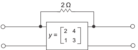
- Calculate the Y parameter for the given network—
-
View Hint View Answer Discuss in Forum
Given network

Y-parameter for network
Standard equations of Y-parameters are
I'1 = Y'11 V1 + Y'12 V2 ........(i)
I'2 = Y'21 V1 + Y'22 V2 .......(ii)
I'1 = – I'2 (from above circuit) ...........(iii)Y'11 = I1 V1 v2 = 0 
From above circuit V1 = 2 I'1 or I'1 = 1 = 0.5 mho V1 2
or Y'11 = 0.5 mhoY'12 = I1 V2 v1 = 0
V2 = I'2 2
or V2 = – I'1 2Y'12 = I1 = – 1 = – 0.5 mho V2 2
SimilarlyY'21 = I'2 V1 v2 = 0 
or Y'21 = – 0.5 mho andY'22 = I2 V2 v1 = 0
or Y'22 = 0.5 mho.
Now,Y' = 0.5 –0.5 and –0.5 0.5
The new Y parameter
Y = Y' + Y''or Y = 0.5 –0.5 2 4 –0.5 0.5 1 3 or Y = 2.5 3.5 and 0.5 3.5 Correct Option: B
Given network
Y-parameter for network
Standard equations of Y-parameters are
I'1 = Y'11 V1 + Y'12 V2 ........(i)
I'2 = Y'21 V1 + Y'22 V2 .......(ii)
I'1 = – I'2 (from above circuit) ...........(iii)Y'11 = I1 V1 v2 = 0 From above circuit V1 = 2 I'1 or I'1 = 1 = 0.5 mho V1 2
or Y'11 = 0.5 mhoY'12 = I1 V2 v1 = 0
V2 = I'2 2
or V2 = – I'1 2Y'12 = I1 = – 1 = – 0.5 mho V2 2
SimilarlyY'21 = I'2 V1 v2 = 0
or Y'21 = – 0.5 mho andY'22 = I2 V2 v1 = 0
or Y'22 = 0.5 mho.
Now,Y' = 0.5 –0.5 and –0.5 0.5
The new Y parameter
Y = Y' + Y''or Y = 0.5 –0.5 2 4 –0.5 0.5 1 3 or Y = 2.5 3.5 and 0.5 3.5
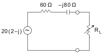
- For the circuit shown below. Calculate the value of load impedance when the load is pure resistive, under maximum power transfer condition—
-
View Hint View Answer Discuss in Forum
Under maximum power transfer condition, when load is pure resistive the load impedance is given by
RL = √R² + (XL or XC)²
Here, R = 60Ω
XC = 80Ω
Now, RL = √60² + 80²
or RL = 100ΩCorrect Option: C
Under maximum power transfer condition, when load is pure resistive the load impedance is given by
RL = √R² + (XL or XC)²
Here, R = 60Ω
XC = 80Ω
Now, RL = √60² + 80²
or RL = 100Ω

