Network Elements and the Concept of Circuit
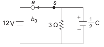
- Switch S in position (a) for a long time and moves to be at t = 0. The value of VC and dVC / dt at t = 0+—
-
View Hint View Answer Discuss in Forum
or IC = - 4 dVC = Ic = - 4 = - 8 V C 1 / 2 dt C 1 / 2 Correct Option: A
or IC = - 4 dVC = Ic = - 4 = - 8 V C 1 / 2 dt C 1 / 2
- A series R-L circuit is initially released. A step voltage is applied to the circuit. If is the time constant of the circuit, the voltage across R and L will be same at time t equal to—
-
View Hint View Answer Discuss in Forum
VL = e – R / L x (t)
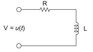
VR = 1 – e – R / L x (t)
(VR + VL = 1)
According to the given condition
VL = VR
e – R / L x (t) = 1 – e – R / L x (t)
or 2 e e – R / L x (t) = 1
or e e – R / L x (t) = 1 / 2
or – R / L x (t) = loge 1 / 2or – t = L (loge 1 – loge 2) R or t = L loge 2 R
or t = loge 2Correct Option: A
VL = e – R / L x (t)
VR = 1 – e – R / L x (t)
(VR + VL = 1)
According to the given condition
VL = VR
e – R / L x (t) = 1 – e – R / L x (t)
or 2 e e – R / L x (t) = 1
or e e – R / L x (t) = 1 / 2
or – R / L x (t) = loge 1 / 2or – t = L (loge 1 – loge 2) R or t = L loge 2 R
or t = loge 2
- For the circuit shown below current to through the inductor is given by the relation—

-
View Hint View Answer Discuss in Forum
Given circuit
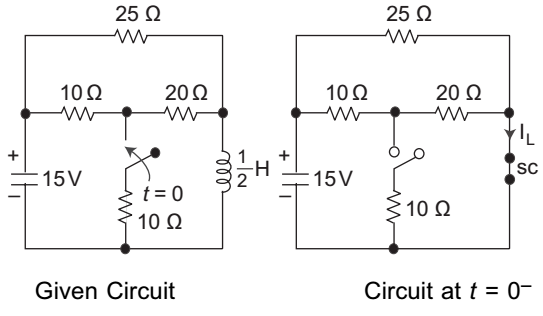
i L (0–) = i L (0+) = 15 where R eq = 25 || (10 + 20) Req 25 × 30 = 25 × 30 Ω 25 + 30 55 or i L (0–) = 15 × 55 = 1.1 amp. 25 × 30
Calculation for i L (∞):
Circuit becomes here the current through the inductor
IL (∞)=I1 + I2I1 = VA – 0 20 = 15 × 10 / 10 + 10 (- 0) = 150 = 3 20 20 x 20 8 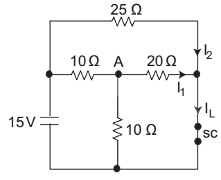
and I2 = 15 = 3 25 8 IL = 3 + 3 = 24 + 15 = 39 1 amp. 5 8 40 40
As we know that the general equation for the current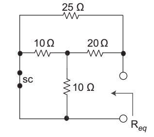
i (t) = [i (0–) – i (∞)] e –t + i (∞) .....(i)
Calculation for the time constant ():= L = 1 / 2 Req [(10 || 100 + 20) || 25] = 1 = 1 2(25 / 2) 25
Now, on putting these values in equation (i), we get.
i (t) = [1.1 – 1] e – t / 1/25 + 1Correct Option: D
Given circuit
i L (0–) = i L (0+) = 15 where R eq = 25 || (10 + 20) Req 25 × 30 = 25 × 30 Ω 25 + 30 55 or i L (0–) = 15 × 55 = 1.1 amp. 25 × 30
Calculation for i L (∞):
Circuit becomes here the current through the inductor
IL (∞)=I1 + I2I1 = VA – 0 20 = 15 × 10 / 10 + 10 (- 0) = 150 = 3 20 20 x 20 8 and I2 = 15 = 3 25 8 IL = 3 + 3 = 24 + 15 = 39 1 amp. 5 8 40 40
As we know that the general equation for the current
i (t) = [i (0–) – i (∞)] e –t + i (∞) .....(i)
Calculation for the time constant ():= L = 1 / 2 Req [(10 || 100 + 20) || 25] = 1 = 1 2(25 / 2) 25
Now, on putting these values in equation (i), we get.
i (t) = [1.1 – 1] e – t / 1/25 + 1
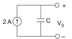
- Which one statement is correct for the circuit given below?
-
View Hint View Answer Discuss in Forum
The output of the given circuit
V0 = 1 ∫ i dt = 1 ∫ 2 dt = 2 C C C 
Which is unstable, because it directly proportional to the time that's why the output of the given circuit unstable in nature.Correct Option: B
The output of the given circuit
V0 = 1 ∫ i dt = 1 ∫ 2 dt = 2 C C C
Which is unstable, because it directly proportional to the time that's why the output of the given circuit unstable in nature.
- Given iL (0+) = 0, VC (0–) = 0 in the steady state VC equals to—

-
View Hint View Answer Discuss in Forum
Apply KVL to the loop
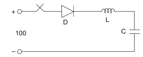
100 = L di(t) dt + 1 C ∫ i (t) dt
taking L.T. to both side, we get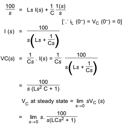
= 100 VCorrect Option: B
Apply KVL to the loop
100 = L di(t) dt + 1 C ∫ i (t) dt
taking L.T. to both side, we get
= 100 V

