Network Elements and the Concept of Circuit
- The 2-port network shown in the circuit given below is connected in parallel with another 2-port network which has y11 = –y12 = –y21 = y22 = Y

The y-parameters of the composite network will satisfy which one of the following?
-
View Hint View Answer Discuss in Forum
Given y11 = –y12 = –y21 = y22 = Y
From figure I1 = 0.V1 + 0V2 ....(A)
I2 = gV1 + 0V2 ....(B)
On comparing equation (A) and (B) with standard equation
I1 = Y11 V1 + Y12 V2
and I2 = Y21 Y1 + Y22 V2,
we get Y21 = g According to the given condition the given 2-port network is connected in parallel with the network whose Y-parameters are given. So, Y-parameters of the composite network will satisfy only option (C).
i.e. Y21 = – y + gCorrect Option: C
Given y11 = –y12 = –y21 = y22 = Y
From figure I1 = 0.V1 + 0V2 ....(A)
I2 = gV1 + 0V2 ....(B)
On comparing equation (A) and (B) with standard equation
I1 = Y11 V1 + Y12 V2
and I2 = Y21 Y1 + Y22 V2,
we get Y21 = g According to the given condition the given 2-port network is connected in parallel with the network whose Y-parameters are given. So, Y-parameters of the composite network will satisfy only option (C).
i.e. Y21 = – y + g
- What is the locus of the tip of the voltage phasor across R in a series R-L-C circuit?
-
View Hint View Answer Discuss in Forum
The locus of the tip of the voltage phasor across R in a series R-L-C circuit will be a circle.
Correct Option: C
The locus of the tip of the voltage phasor across R in a series R-L-C circuit will be a circle.
- Consider the following circuit:

If V1 = 5V and V2 = 3 V, then what is the input impedance of the CRO in the above circuit?
-
View Hint View Answer Discuss in Forum
The given circuit.
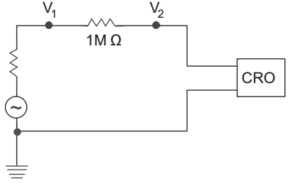
Let the input impedance of CRO is R2 the given circuit can be redrawn as shown below
Applying voltage divider ruleV2 = V1 × R2 R1 + R2 3V = 5 V × R2 1 MΩ + R2
or 5R2 = 3 R2 + 3
or 2R2 = 3
or R2 = 1.5 MΩCorrect Option: B
The given circuit.
Let the input impedance of CRO is R2 the given circuit can be redrawn as shown below
Applying voltage divider ruleV2 = V1 × R2 R1 + R2 3V = 5 V × R2 1 MΩ + R2
or 5R2 = 3 R2 + 3
or 2R2 = 3
or R2 = 1.5 MΩ
- Consider the following circuit:

What is power delivered to resistor R in the above circuit?
-
View Hint View Answer Discuss in Forum
The given circuit
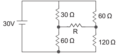
The given circuit can be redrawn as shown below.
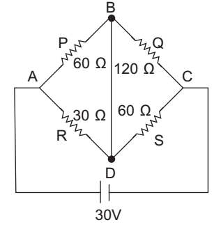
From above figure
P/Q = R/S
i.e.
60/120 = 30/60 (Wheatstone bridge)
Therefore, power delivered to resistor R is zero watt.Correct Option: B
The given circuit
The given circuit can be redrawn as shown below.
From above figure
P/Q = R/S
i.e.
60/120 = 30/60 (Wheatstone bridge)
Therefore, power delivered to resistor R is zero watt.
- Consider the following circuit:

In the above circuit, the current I2 is 2 A when the value of R1 is 20Ω. What will be the value of I2 when R1 is changed to 10Ω?
-
View Hint View Answer Discuss in Forum
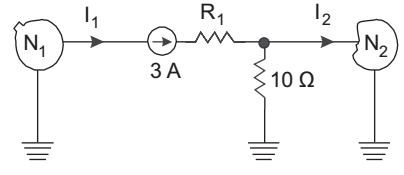
Since the resistance R is connected to a constant current source, therefore, the value of I2 will remain the same.Correct Option: B
Since the resistance R is connected to a constant current source, therefore, the value of I2 will remain the same.

