Network Elements and the Concept of Circuit
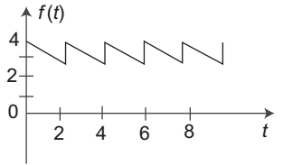
- D.C. component of the waveform shown below is—
-
View Hint View Answer Discuss in Forum
Here equation of f (t) = mt + 4
f (t) = 
– 1 t + 4 
2
where, m = slope of the given waveformNow, D.C. component = 1 
f(t) dt T T = 1 2 – (t/2) + 4 dt 2 0 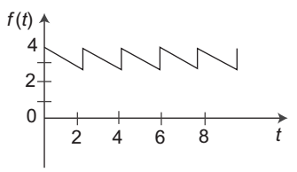
= 1 
–t2 + 4t 
2 2 4 0 = 1 –4 + 4 × 2 2 4
= 3.5 VCorrect Option: D
Here equation of f (t) = mt + 4
f (t) = – 1 t + 4 2
where, m = slope of the given waveformNow, D.C. component = 1 f(t) dt T T = 1 2 – (t/2) + 4 dt 2 0 = 1 –t2 + 4t 2 2 4 0 = 1 –4 + 4 × 2 2 4
= 3.5 V
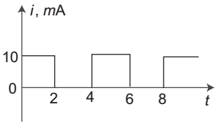
- D.C. component of the waveform shown below is—
-
View Hint View Answer Discuss in Forum
D.C. component = 1 f(t) dt T T 
= 1 4 f(t) dt 4 0 = 1 2 10 dt + 4 0 dt 4 0 2 = 20 = 5mA 4 Correct Option: C
D.C. component = 1 f(t) dt T T = 1 4 f(t) dt 4 0 = 1 2 10 dt + 4 0 dt 4 0 2 = 20 = 5mA 4
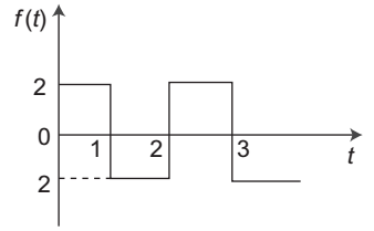
- D.C. component of the waveform shown below is—
-
View Hint View Answer Discuss in Forum
Average value = D.C. component of wave
= 1 f(t) dt = 1 2 f(t) dt T T 2 0 
= 1 1 (2) dt + 2 (–2) dt 2 0 1 = 1 [(2t)10 + (–2t)21] 2 = 1 [2 – 4 + 2] = 0 2 Correct Option: D
Average value = D.C. component of wave
= 1 f(t) dt = 1 2 f(t) dt T T 2 0 = 1 1 (2) dt + 2 (–2) dt 2 0 1 = 1 [(2t)10 + (–2t)21] 2 = 1 [2 – 4 + 2] = 0 2
- The 2-port network of fig. (1) has Y-parameter .The network is excited as shown in fig. (2). If IX = IY, the current I drawn from the source would be—

-
View Hint View Answer Discuss in Forum
From the figure (1)
I1 = V1 Y11 + V2 Y12 (i)
I2 = V1 Y21 + V2 Y22 (ii)
As from the figure (2) it is clear that terminal 2 and terminal 1 are at the same potential i.e.
V1 = V2 = V
and I = I1 + I2
or I = V (Y11 + Y12) + V (Y21 + Y22)
or I = V (Y11 + Y12 + Y21 + Y22)Correct Option: A
From the figure (1)
I1 = V1 Y11 + V2 Y12 (i)
I2 = V1 Y21 + V2 Y22 (ii)
As from the figure (2) it is clear that terminal 2 and terminal 1 are at the same potential i.e.
V1 = V2 = V
and I = I1 + I2
or I = V (Y11 + Y12) + V (Y21 + Y22)
or I = V (Y11 + Y12 + Y21 + Y22)
- The time constant of the network shown in the figure is—
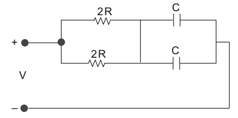
-
View Hint View Answer Discuss in Forum
τ = R eq. C eq Ceq = C + C = 2C
so, time constant Req = 2R . 2R = R 2R + 2R
τ = R. 2C = 2RCCorrect Option: A
τ = R eq. C eq Ceq = C + C = 2C
so, time constant Req = 2R . 2R = R 2R + 2R
τ = R. 2C = 2RC

