Power electronics and drives miscellaneous
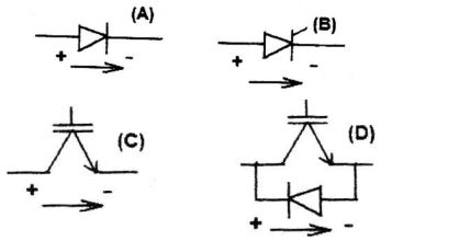
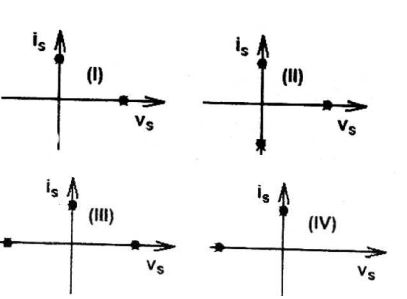
- Match the switch arrangements on the top row to the steady-state V-I characteristics on the lower row. The steady state operating points are shown by large black dots.
-
View Hint View Answer Discuss in Forum

Negative voltage, current = 0Correct Option: C

Negative voltage, current = 0
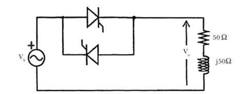
- In the single phase voltage controller circuit shown in the figure given below, for what range of triggering angle (α), the output voltage (v0) is not controllable?
-
View Hint View Answer Discuss in Forum
R + jXL = (50 + j 50) Ω
∴ tan φ = ω L = XL = 50 = 1 R R 50
⇒ φ = 45°
Hence firing angle α must be greater than 45° Thus for 0 < α < 45°, VO is uncontrollable.
Correct Option: A
R + jXL = (50 + j 50) Ω
∴ tan φ = ω L = XL = 50 = 1 R R 50
⇒ φ = 45°
Hence firing angle α must be greater than 45° Thus for 0 < α < 45°, VO is uncontrollable.
- The equivalent circuits of a diode, during forward biased and reverse biased conditions, are shown in the figure given below.
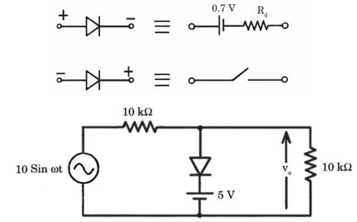
If such a diodes is used in clipper circuit of figure given above, the output voltage (v0) of the circuit will be
-
View Hint View Answer Discuss in Forum
During +ve cycle of input voltage, Vi,
When Vi > 5.7 volts
Diode becomes forward-biased and the circuit will be as shown here
Rf is the diode forward resistance.
Output voltage, V0 = 5.7 + RfI
During – ve cycle of input voltage Vi, Diode D is reversed-biased and cut-off.
The circuit will be as shown below.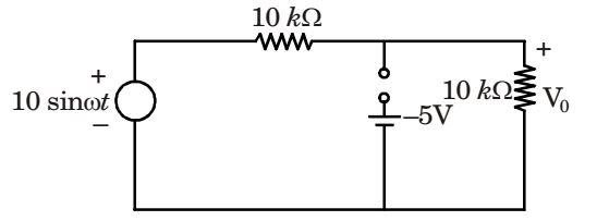
V0 = 10 sinωt . 10 kΩ = 5 sinωt 10 kΩ + 10 kΩ
Correct Option: A
During +ve cycle of input voltage, Vi,
When Vi > 5.7 volts
Diode becomes forward-biased and the circuit will be as shown here
Rf is the diode forward resistance.
Output voltage, V0 = 5.7 + RfI
During – ve cycle of input voltage Vi, Diode D is reversed-biased and cut-off.
The circuit will be as shown below.
V0 = 10 sinωt . 10 kΩ = 5 sinωt 10 kΩ + 10 kΩ
- A 3-phase Voltage Source Inverter is operated in 180° conduction mode. Which one of the following statements is true?
-
View Hint View Answer Discuss in Forum
Line voltage,

For n = 3, VL = 0. as cos 
nπ 
= 0 6
Pole voltage,
For n = 3, VP ≠ 0.
Hence it is not free from third hormonics.Correct Option: B
Line voltage,

For n = 3, VL = 0. as cos 
nπ 
= 0 6
Pole voltage,
For n = 3, VP ≠ 0.
Hence it is not free from third hormonics.
- In the chopper circuit shown, the main thyristor (TM) is operated at a duty ratio of 0.8 which is
much larger the commutation interval. If the maximum allowable reapplied dv on TM dt
is 50 V/μs, what should be the theoretical minimum value of C1? Assume current ripple through L0 to be negligible.
-
View Hint View Answer Discuss in Forum
I0 = 100 = 12.5 amp 0.8
Duty ratio of TM = 0.8
∴ Current through M, IM = 12.5 × 0.8 = 10ANow IM = C dVM dt ∴ 10 = C × 50 10-6 or C = 50 × 10-6 = 0.2 μF 10
Correct Option: A
I0 = 100 = 12.5 amp 0.8
Duty ratio of TM = 0.8
∴ Current through M, IM = 12.5 × 0.8 = 10ANow IM = C dVM dt ∴ 10 = C × 50 10-6 or C = 50 × 10-6 = 0.2 μF 10

