-
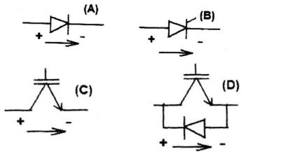
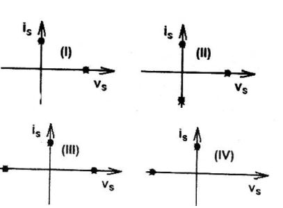
Match the switch arrangements on the top row to the steady-state V-I characteristics on the lower row. The steady state operating points are shown by large black dots.


-
- A - I , B - II , C - III , D - IV
- A - II , B - IV , C - I , D - III
- A - IV , B - III , C - I , D - II
- A - IV , B - III , C - II , D - I
Correct Option: C

Negative voltage, current = 0

