Power electronics and drives miscellaneous
- In the following chopper duty ratio of switch S is 0.4. If the inductor and capacitor are sufficiently large to ensure continuous inductor current and ripple free capacitor voltage, the charging current (in Ampere) of the 5V battery, under steady-state, is _____________ .

-
View Hint View Answer Discuss in Forum
V0 = DVS = 0.4 × 20 = 8 V
I0 = V0 - E = 8 - 5 = 3 = 1 A R 3 3 Correct Option: A
V0 = DVS = 0.4 × 20 = 8 V
I0 = V0 - E = 8 - 5 = 3 = 1 A R 3 3
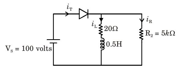
- An SCR having a turn ON time of 5 μsec, latching current of 50 mA and holding current of 40 mA is triggered by a short duration pulse and is used in the circuit shown in the figure given below. The minimum pulse width required to turn the SCR ON will be

-
View Hint View Answer Discuss in Forum

iR = 100 = 100 = 0.02 A R2 5 × 103 = 100 
1 - e{-20t / 0.5} 
= 5(1 - e-40t) 20
Then, iT = iL + iR = 0.02 + 5(1 – e – 40t)
It minimum pulse width is T for ia ≥ latching current.
Then, 0.02 + 5(1 – e – 40t) = 0.05
⇒ 5(1 – e – 0.40t) = 0.03
⇒ t = 150 μ sec.Correct Option: A

iR = 100 = 100 = 0.02 A R2 5 × 103 = 100 
1 - e{-20t / 0.5} 
= 5(1 - e-40t) 20
Then, iT = iL + iR = 0.02 + 5(1 – e – 40t)
It minimum pulse width is T for ia ≥ latching current.
Then, 0.02 + 5(1 – e – 40t) = 0.05
⇒ 5(1 – e – 0.40t) = 0.03
⇒ t = 150 μ sec.
- A single-phase bridge converter is used to charge a battery of 200 V having an internal resistance of 0.2 Ω as shown in the figure given below. The SCRs are triggered by a constant dc signal. If SCR 2 gets open circuited, then what will be the average charging current?

-
View Hint View Answer Discuss in Forum
Average current is given by,

= 1 [2Vm cosθ - E(π - 2θ1)] 2πR where , θ1 = sin-1 
E 
Vm = sin-1 
200 
= 38° = 6.66 rad 230 √2 Then , Iavg = 1 2π × 2 Iavg = 1 [2 √2 × 230 cos38° - 200(π - 2 × 0.66)] = 11.9 2π × 2 Correct Option: A
Average current is given by,

= 1 [2Vm cosθ - E(π - 2θ1)] 2πR where , θ1 = sin-1 
E 
Vm = sin-1 
200 
= 38° = 6.66 rad 230 √2 Then , Iavg = 1 2π × 2 Iavg = 1 [2 √2 × 230 cos38° - 200(π - 2 × 0.66)] = 11.9 2π × 2
- A solar cell of 350 V is feeding power t o an ac supply of 440 V, 50 Hz through a 3-phase fully controlled bridge converter. A large inductance is connected in the dc circuit to maintain the dc current at 20 A. If the solar cell resistance is 0.5 Ω, then each thyristor will be reverse biased for a period of
-
View Hint View Answer Discuss in Forum
Voltage across 3-φ fully controlled bridge converter
V0 = – (E – Idc Rcell)
= – (350 – 20 × 0.5) = – 340Vi.e. , V0 = -340 = 3Vme cos α π ⇒ 3 × 440 √2 cos α = - 340 π
⇒ α = 125°
Thus, each thyristor will be reversed biased for a period of (180° – 125°) = 55°Correct Option: A
Voltage across 3-φ fully controlled bridge converter
V0 = – (E – Idc Rcell)
= – (350 – 20 × 0.5) = – 340Vi.e. , V0 = -340 = 3Vme cos α π ⇒ 3 × 440 √2 cos α = - 340 π
⇒ α = 125°
Thus, each thyristor will be reversed biased for a period of (180° – 125°) = 55°
- A voltage commutation circuit is shown in the figure given below. If the turn off time of the SCRs is 50 μ sec and a safety margin of 2 is considered, then what will be the approximate minimum value of capacitor required for proper commutation?

-
View Hint View Answer Discuss in Forum
Firing of TH1 thyristor would commute TH2 and firing of TH2 would commute TH1 and in this way load will be transfered between TH1 and TH2 and vice-versa.
Circuit turn-off time for,
TH1, t1 = R1C ln 2
and turn-off time for
TH2, t2 = R2C ln 2
Safety margin = 2
Then, t1 = t2 = 2 × 50 × 10– 6 (given)
⇒ R1 C ln2 = 2 × 50 × 10– 6⇒ C = 2 × 50 × 10– 6 = 2.88 μF 50 × ln 2
Correct Option: A
Firing of TH1 thyristor would commute TH2 and firing of TH2 would commute TH1 and in this way load will be transfered between TH1 and TH2 and vice-versa.
Circuit turn-off time for,
TH1, t1 = R1C ln 2
and turn-off time for
TH2, t2 = R2C ln 2
Safety margin = 2
Then, t1 = t2 = 2 × 50 × 10– 6 (given)
⇒ R1 C ln2 = 2 × 50 × 10– 6⇒ C = 2 × 50 × 10– 6 = 2.88 μF 50 × ln 2

