Power electronics and drives miscellaneous
- A 3-phase fully controlled bridge converter with free wheeling diode is fed from 400 V, 50 Hz AC source and is operating at a firing angle of 60°. The load current is assumed constant at 10 A due to high load inductance. The input displacement factor (IDF) and the input power factor (IPF) of the converter will be
-
View Hint View Answer Discuss in Forum
For 3-φ full-wave converter,
RMS value of source current,
RMS value of nth harmonic current,ISh = 4I0 sin nπ √2 nπ 3
For fundamental component,IS1 = 2 √2 I0 sin π = √6 I0 π 3 π
Then, CDF (current displacement factor)
and input displacement factor, (IDF) cos α = cos 60° = 0.5
Input power factor, IPF = IDF × CDF = 0.5 × 0.955 ≅ 0.478Correct Option: C
For 3-φ full-wave converter,
RMS value of source current,
RMS value of nth harmonic current,ISh = 4I0 sin nπ √2 nπ 3
For fundamental component,IS1 = 2 √2 I0 sin π = √6 I0 π 3 π
Then, CDF (current displacement factor)
and input displacement factor, (IDF) cos α = cos 60° = 0.5
Input power factor, IPF = IDF × CDF = 0.5 × 0.955 ≅ 0.478
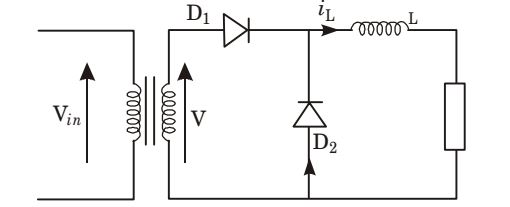
- A single-phase half wave uncontrolled converter circuit is shown in the figure given below. A 2– winding transformer is used at the input for isolation. Assuming the load current to be constant and v = Vm sin ωt, the current waveform through diode D2 will be

-
View Hint View Answer Discuss in Forum
During 0 < ωt < π, Diode D1 is forward-biased and diode D2 sets reversed-biased.
During π < ωt < 2π , diode D1 is reversed-biased and diode D2 is forward-biased.
Thus, in π < ωt < 2π, diode D2 starts conduct, and in π < ωt < 2π , there is no current flows.Correct Option: D
During 0 < ωt < π, Diode D1 is forward-biased and diode D2 sets reversed-biased.
During π < ωt < 2π , diode D1 is reversed-biased and diode D2 is forward-biased.
Thus, in π < ωt < 2π, diode D2 starts conduct, and in π < ωt < 2π , there is no current flows.
- The speed of a 3– phase, 440 V, 50 Hz induction motor is to be controlled over a wide range from zero speed to 1.5 time the rated speed using a 3-phase voltage source inverter. It is desired to keep the flux in the machine constant in the constant torque region by controlling the terminal voltage as the frequency changes. The inverter out put voltage vs frequency characteristic should be
-
View Hint View Answer Discuss in Forum
For speed control by varying frequency method, ratio V must be kept constant, f
so that maximum flux density may remain constant. i.e.,
⇒ V = 4.44 Nf Bm A⇒ V = 4.44 N Bm A = constant f
But for frequency above 50 Hz, voltage can’t be increased alone rated voltage. So, above 50 Hz voltage kept constant.Correct Option: A
For speed control by varying frequency method, ratio V must be kept constant, f
so that maximum flux density may remain constant. i.e.,
⇒ V = 4.44 Nf Bm A⇒ V = 4.44 N Bm A = constant f
But for frequency above 50 Hz, voltage can’t be increased alone rated voltage. So, above 50 Hz voltage kept constant.
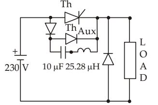
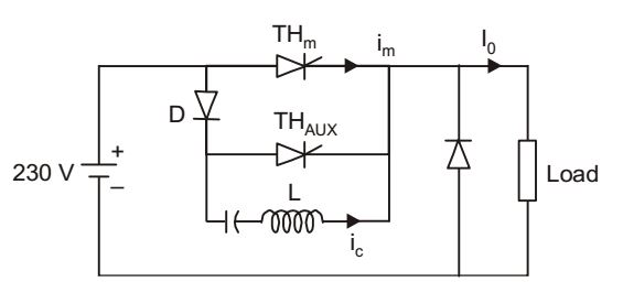
- The circuit in the figure is a current commutated dc – dc chopper where, ThM is the main SCR and ThAUX is the auxiliary SCR. The load current is constant at 10 A. ThM is ON. ThAUX is triggered at t = 0. ThM is turned OFF between

-
View Hint View Answer Discuss in Forum

For t < 0, Vc = Vs, ic = 0 and iT1 = I0
At t = 0, THAUX is trigered, and a resonant Current i c designs to flow from C through THAUX, L and back to c.
The resonant current is given by,
At t1 = π , ic = 0 and Vc = -Vs ω0
Since iC gets reverses, THAUX is off.
For Vc = – Vs , resonant current ic flows through C, L, D and THm. Because this current ic flows and builds up in opposite direction to forward current of THm Then,
im = Io – ic = Io – Ip sin ω∆t
when im = 0, THm gets turned offi.e. , ∆t = 1 sin-1 
Io 
ω0 Ip
Hence, THm is off between t1 < t < t1 + ∆tt1 = π = π√LC = π√10 × 25.28 sec = 50 sec. ω0
i.e., commutation time given by 50 µs < t < 75sCorrect Option: B

For t < 0, Vc = Vs, ic = 0 and iT1 = I0
At t = 0, THAUX is trigered, and a resonant Current i c designs to flow from C through THAUX, L and back to c.
The resonant current is given by,
At t1 = π , ic = 0 and Vc = -Vs ω0
Since iC gets reverses, THAUX is off.
For Vc = – Vs , resonant current ic flows through C, L, D and THm. Because this current ic flows and builds up in opposite direction to forward current of THm Then,
im = Io – ic = Io – Ip sin ω∆t
when im = 0, THm gets turned offi.e. , ∆t = 1 sin-1 
Io 
ω0 Ip
Hence, THm is off between t1 < t < t1 + ∆tt1 = π = π√LC = π√10 × 25.28 sec = 50 sec. ω0
i.e., commutation time given by 50 µs < t < 75s
- A three-phase, 440 V, 50 Hz ac mains fed thyristor bridge is feeding a 440 V dc, 15 kW. 1500 rpm separately excited dc motor with a ripple free continuous current in the dc link under all operating conditions. Neglecting the losses, the power factor of the ac mains at half the rated speed, is
-
View Hint View Answer Discuss in Forum
Back emf of separately excited motor, Ea ∝ N (speed of the motor).
As losses are neglected, Ia2 ra ≈ O
then, by Vt – Ia2 ra = Ea
we get, Vt ≈ Ea ∝ N
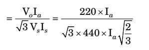
When the speed is reduced by half of rated speed output voltage of the bridge also get reduced by halfRMS value of the supply current, Is = Ia√ 2 3
Power delivered to motor, Po = Vo Ia
Input power to thyristor, Pin = √3 Vs Is ,Hence, Input power factor, Po Pin 
= 0.354
Correct Option: A
Back emf of separately excited motor, Ea ∝ N (speed of the motor).
As losses are neglected, Ia2 ra ≈ O
then, by Vt – Ia2 ra = Ea
we get, Vt ≈ Ea ∝ N
When the speed is reduced by half of rated speed output voltage of the bridge also get reduced by halfRMS value of the supply current, Is = Ia√ 2 3
Power delivered to motor, Po = Vo Ia
Input power to thyristor, Pin = √3 Vs Is ,Hence, Input power factor, Po Pin 
= 0.354

