Power electronics and drives miscellaneous
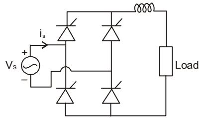
- A fully controlled converter bridge feeds a highly inductive load with ripple free load current. The input supply (vs) to the bridge is a sinusoidal source. Triggering angle of the bridge converter is α = 30°. The input power factor of the bridge is ___.
-
View Hint View Answer Discuss in Forum
Pin = V s,rms I s,rms cos φ = V0 I0
⇒ cos φ = V0 I0 [Since I0 = I s,rms ] V s,rms I s,rms = V0 V s,rms cos φ = 2 √2 Vs cos30° = 0.779 π Vs
Correct Option: A
Pin = V s,rms I s,rms cos φ = V0 I0
⇒ cos φ = V0 I0 [Since I0 = I s,rms ] V s,rms I s,rms = V0 V s,rms cos φ = 2 √2 Vs cos30° = 0.779 π Vs
- The figure shows one period of the output voltage of an inverter. α should be chosen such that 60° < α < 90°. If rms value of the fundamental component is 50V, then α in degree is __________.

-
View Hint View Answer Discuss in Forum

= 4Vs [1 - cosα - cosα + 0] π = 4Vs [1 - 2 cosα] π RMS Value of V01 = 4Vs [1 - 2 cosα] π √2 ⇒ 50 = 400 [1 - 2 cosα] π √2
α = 77.15°
Correct Option: B

= 4Vs [1 - cosα - cosα + 0] π = 4Vs [1 - 2 cosα] π RMS Value of V01 = 4Vs [1 - 2 cosα] π √2 ⇒ 50 = 400 [1 - 2 cosα] π √2
α = 77.15°
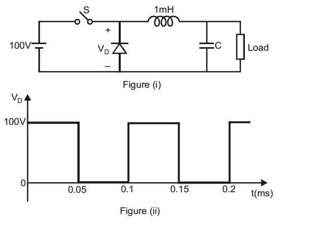
- Figure (i) shows the circuit diagram of a chopper. The switch S in the circuit in Figure (i) is switched such that the voltage VD across the diode has the wave shape as shown in Figure (ii). The capacitance C is large so that the voltage across it is constant. If switch S and the diode are ideal, the peak to peak ripple (in A) in the inductor current is __________
-
View Hint View Answer Discuss in Forum
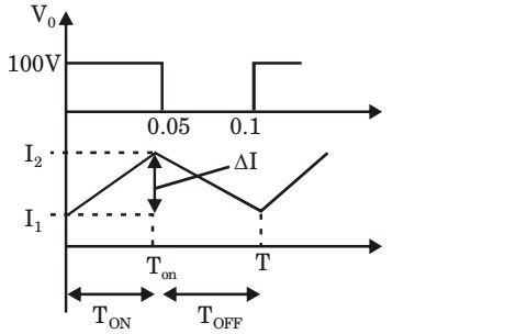
Peak to peak ripple in inductor current in∆I = Vs - Vo Tm L = 100 - 
100 × 0.05 
× 0.05 × 10-3 0.1 1 × 10-3
= 50 × 0.05
⇒ ∆I = 2.5 A
Correct Option: C

Peak to peak ripple in inductor current in∆I = Vs - Vo Tm L = 100 - 
100 × 0.05 
× 0.05 × 10-3 0.1 1 × 10-3
= 50 × 0.05
⇒ ∆I = 2.5 A
- The figure shows the circuit diagram of a rectifier. The load consists of a resistance 10 Ω and an inductance 0.05H connected in series. Assuming ideal thyristor and ideal diode, the thyristor firing angle (in degree) needed to obtain an average load voltage of 70V is ____________.

-
View Hint View Answer Discuss in Forum
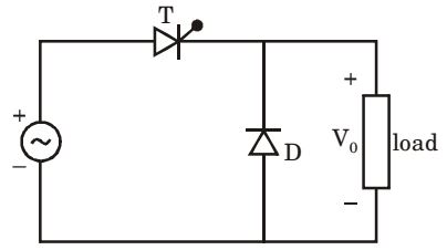
V0 = 70v; Load, R = 10Ω ; L = 0.05H
Firing angled = ?
The o/p volt of given converter isV0 = Vm [1 + cosα] 2π 70 = 525 [1 + cosα] 2π
α = 69.3°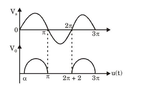
Correct Option: A

V0 = 70v; Load, R = 10Ω ; L = 0.05H
Firing angled = ?
The o/p volt of given converter isV0 = Vm [1 + cosα] 2π 70 = 525 [1 + cosα] 2π
α = 69.3°
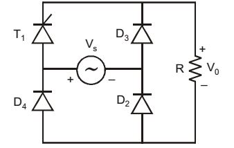
- In the given rectifier, the delay angle of the thyristor T1 measured from the positive going zero crossing of Vs is 30°. If the input voltage Vs is 100 sin(100πt)V, the average voltage across R (in Volt) under steady-state is _____________.
-
View Hint View Answer Discuss in Forum
Given : α = 30° ,
Vin = 100 sin(l00πt)Now , V0 = Vm [3 + cosα] 2π = 100 [3 + cos30°] = 61.52 V 2π Correct Option: B
Given : α = 30° ,
Vin = 100 sin(l00πt)Now , V0 = Vm [3 + cosα] 2π = 100 [3 + cos30°] = 61.52 V 2π

