Analog circuits miscellaneous
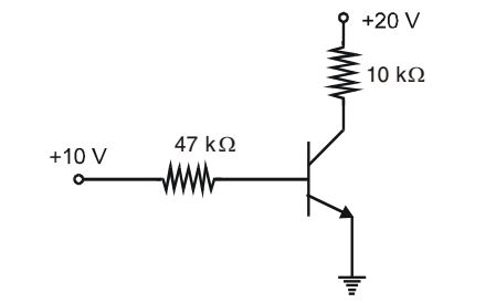
- In the transistor circuit shown below, the collector to ground voltage is + 20 V.

The possible condition is
-
View Hint View Answer Discuss in Forum
NA
Correct Option: B
NA
- The gain bandwidth product of a two stage CE amplifier is
-
View Hint View Answer Discuss in Forum
NA
Correct Option: A
NA
- The base-biased transistor circuit of figure is subjected to increase in junction temperature from 25°C to 75°. If β increases from 100 to 150 with rising temperature, percentage change in a-point value (IC, VCE) over the temperature range will be (assume VBE reacts at 0.7 V)

-
View Hint View Answer Discuss in Forum
IB = VCC - VBE = 12 - 0.7 = 0.113 mA RB 100 × 103
IC = β IB = 100 × 0.113 = 11.3 mA
VCE = VCC - IC RC
= 12 – (11.3 × 10–3 × 500) = 5.35 V
At 75° C IB = 0.113 mA
IC = β IB = 150 × 0.113 = 16.95 mA
VCE = 12 – (16.95 × 10–3 × 500) = 3.32 V∴ ∆IC = 16.75 - 1.3 × 100 = 50% (increased) 11.3 and ∆ VCE = 3.52 - 6.35 × 100 = -44.57% (decreased) 11.3 Correct Option: B
IB = VCC - VBE = 12 - 0.7 = 0.113 mA RB 100 × 103
IC = β IB = 100 × 0.113 = 11.3 mA
VCE = VCC - IC RC
= 12 – (11.3 × 10–3 × 500) = 5.35 V
At 75° C IB = 0.113 mA
IC = β IB = 150 × 0.113 = 16.95 mA
VCE = 12 – (16.95 × 10–3 × 500) = 3.32 V∴ ∆IC = 16.75 - 1.3 × 100 = 50% (increased) 11.3 and ∆ VCE = 3.52 - 6.35 × 100 = -44.57% (decreased) 11.3
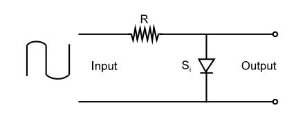
- For the given input, output waveform across the diode shown in the figure will be

-
View Hint View Answer Discuss in Forum
The diode will not conduct in the negative half of the wave and while it conducts, there will be a small voltage drop across it, shown as 0.06 V on (d)
Correct Option: D
The diode will not conduct in the negative half of the wave and while it conducts, there will be a small voltage drop across it, shown as 0.06 V on (d)
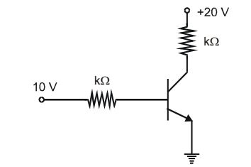
- In the transistor circuit shown in the figure, collector-to-ground voltage is +20 V. Which of the following is the probable error?

-
View Hint View Answer Discuss in Forum
For collector to ground which is the same as emitter terminal to read full supply voltage at 20 V, no current should be drawn and this can happen if emitter to ground connection is open as then there will be neither IH or IC.
Correct Option: B
For collector to ground which is the same as emitter terminal to read full supply voltage at 20 V, no current should be drawn and this can happen if emitter to ground connection is open as then there will be neither IH or IC.

