Analog circuits miscellaneous
- A voltage source VAB = 4 sinωt is applied to the terminals A and B of the circuit shown in the given figure. The diodes are assumed to be ideal. The impedance by the circuit across the terminals A and B is _________ kΩ .

-
View Hint View Answer Discuss in Forum
Diode D1 conducts through 10 kΩ on the extreme right and diode D2 is blocked. Diode D2 conducts through 10 kΩ in the middle branch and diode D1 is blocked. Thus source always sees a resistance of 10 kΩ.
Correct Option: A
Diode D1 conducts through 10 kΩ on the extreme right and diode D2 is blocked. Diode D2 conducts through 10 kΩ in the middle branch and diode D1 is blocked. Thus source always sees a resistance of 10 kΩ.
- In the circuit shown in the given figure, transistor is in the active mode. VBE = 0.7 volt. The best approximation without knowing hfe for VC as shown in the figure is _________ V

-
View Hint View Answer Discuss in Forum
IC ≃ IE = (4 - 0.7) volt = 1 mA 3.3 kΩ
∴ VC = 8 – 3.7 × 1 = 4.3 volts .
Correct Option: C
IC ≃ IE = (4 - 0.7) volt = 1 mA 3.3 kΩ
∴ VC = 8 – 3.7 × 1 = 4.3 volts .
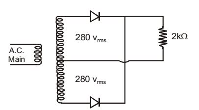
- The centre tap full-wave single-phase rectifier circuit uses 2 diodes as shown in the given figure. The rms voltage across each diode is _________ V
-
View Hint View Answer Discuss in Forum
PIV across each diode = 2 × 280 √2 volts.
When diode is conducting (during half cycle) voltage across the diode is zero.
Hence rms value of the voltage across the diode= PIV = 280 √2 = 395.3 V 2 Correct Option: B
PIV across each diode = 2 × 280 √2 volts.
When diode is conducting (during half cycle) voltage across the diode is zero.
Hence rms value of the voltage across the diode= PIV = 280 √2 = 395.3 V 2
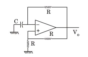
- For the oscillator circuit shown in the given figure, expression for the time period of oscillation can be given by (where t = RC)
-
View Hint View Answer Discuss in Forum
T = 2RC ln 1 + β 1 - β Here , β = 1 = R 2 R + R
∴ T = 2 RC ln 3 = 2 τ ln 3Correct Option: B
T = 2RC ln 1 + β 1 - β Here , β = 1 = R 2 R + R
∴ T = 2 RC ln 3 = 2 τ ln 3
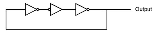
- The circuit shown in the figure
-
View Hint View Answer Discuss in Forum
NA
Correct Option: A
NA

