Network theory miscellaneous
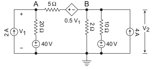
- For the circuit shown below, the V1 = ?
-
View Hint View Answer Discuss in Forum
The given circuit

Applying KCL at node AV1 - 20 + V1 - 0.5V1 - V2 = 2 20 5
orV1 
1 + 1 
- V2 = 3 20 10 5
or3V1 - V2 = 3 20 5
or
3V1 – 4V2 = 60 . . . . . . …(i)
KCL at node BV2 - V1 + 0.5V1 + V2 + V2 - 40 = 4 5 2 10 V2 1 + 1 + 1 - V1 = 8 5 2 10 10
orV2 2 + 5 + 1 - V1 = 8 10 8
or
8V1 – V1 = 80 …. . . (ii)
From equation (i) and (ii)
V1 = 40V and V2 = 15V
Hence alternative (A) is the correct choice.Correct Option: A
The given circuit
Applying KCL at node AV1 - 20 + V1 - 0.5V1 - V2 = 2 20 5
orV1 1 + 1 - V2 = 3 20 10 5
or3V1 - V2 = 3 20 5
or
3V1 – 4V2 = 60 . . . . . . …(i)
KCL at node BV2 - V1 + 0.5V1 + V2 + V2 - 40 = 4 5 2 10 V2 1 + 1 + 1 - V1 = 8 5 2 10 10
orV2 2 + 5 + 1 - V1 = 8 10 8
or
8V1 – V1 = 80 …. . . (ii)
From equation (i) and (ii)
V1 = 40V and V2 = 15V
Hence alternative (A) is the correct choice.
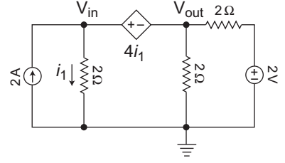
- For the circuit shown below, the Vout =?
-
View Hint View Answer Discuss in Forum
The given circuit:
Applying nodal equation for supernodeVin + Vout + Vout - 2 = 2 2 2 2
or
Vin + 2 Vout = 6 . . . . …(i)
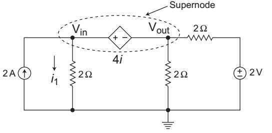
Again writting constraint equation for the dependent source inside the supernode. The dependent source voltage inside the supernode must satisfy.
Vin – Vout = 4i1
or
Vin – Vout = 4 Vin/2
or
Vin + Vout = 0 . . . …(ii)
From equation (i) and (ii) we get
Vout = 6V.Correct Option: A
The given circuit:
Applying nodal equation for supernodeVin + Vout + Vout - 2 = 2 2 2 2
or
Vin + 2 Vout = 6 . . . . …(i)
Again writting constraint equation for the dependent source inside the supernode. The dependent source voltage inside the supernode must satisfy.
Vin – Vout = 4i1
or
Vin – Vout = 4 Vin/2
or
Vin + Vout = 0 . . . …(ii)
From equation (i) and (ii) we get
Vout = 6V.
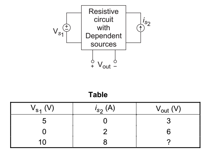
- A linear resistive circuit has two inputs Vs1 and is2 with output Vout, as shown below. Table below shows the result of two sets of measurement taken in laboratory. Find the output voltage when the inputs are Vs1 = 10V and is2 = 8A.
-
View Hint View Answer Discuss in Forum
From the linearity relation and from the given circuit

Vout = AVs1 + Bis2 ⇒ (A) for appropriate A and B. The data from table imply that
3 = A × 5 + B × 0, which gives A = 0·6
Here A is dimensionless because Vout and Vs1 are both voltages.
Also, 6 = A × 0 + B × 2, which gives B = 3Ω
Here B has the unit of ohm. Therefore, the linear equation relating Vs1 and i s2 to Vout is
Vout = 0·6Vs1 + 3is2
Now, when Vs1 = 10V and is2 = 8A then
Vout = 0·6 × 10 + 3 × 8 = 30V.Correct Option: A
From the linearity relation and from the given circuit
Vout = AVs1 + Bis2 ⇒ (A) for appropriate A and B. The data from table imply that
3 = A × 5 + B × 0, which gives A = 0·6
Here A is dimensionless because Vout and Vs1 are both voltages.
Also, 6 = A × 0 + B × 2, which gives B = 3Ω
Here B has the unit of ohm. Therefore, the linear equation relating Vs1 and i s2 to Vout is
Vout = 0·6Vs1 + 3is2
Now, when Vs1 = 10V and is2 = 8A then
Vout = 0·6 × 10 + 3 × 8 = 30V.
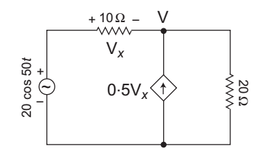
- The average power delivered by the dependent current source for the circuit shown below—
-
View Hint View Answer Discuss in Forum
The given circuit:

From figureV – 20 0° + V = 0·5Vx ......…(i) 10 20
and V – 20 0° = – Vx
or
Vx = 20 0° – V …(ii)Now, V – 20 0° + V = 0·5 [20 0° – V] 10 20
orV 1 + 1 + 1 = 2 0° + 10 0° 10 20 2
or
V = 18·46 0°
and
Vx = 20 0° – V = 20 0° – 18·46 0°
= 1·54 0°
Hence power delivered by the dependent source= V × 0·5Vx i.e. Vm Im cos θ 2 2 = 18·46 × 0·5 × 1·54 2
= 7·107W
Hence alternative (D) is the correct choice.Correct Option: D
The given circuit:
From figureV – 20 0° + V = 0·5Vx ......…(i) 10 20
and V – 20 0° = – Vx
or
Vx = 20 0° – V …(ii)Now, V – 20 0° + V = 0·5 [20 0° – V] 10 20
orV 1 + 1 + 1 = 2 0° + 10 0° 10 20 2
or
V = 18·46 0°
and
Vx = 20 0° – V = 20 0° – 18·46 0°
= 1·54 0°
Hence power delivered by the dependent source= V × 0·5Vx i.e. Vm Im cos θ 2 2 = 18·46 × 0·5 × 1·54 2
= 7·107W
Hence alternative (D) is the correct choice.
- The impedance matrices of two, two-port networks are given by
3 2 and 15 5 2 3 5 25
If these two networks are connected in series, the impedance matrix of the resulting two port network will be—
-
View Hint View Answer Discuss in Forum
The given matrices are:
3 2 and 15 5 2 3 5 26
When the two networks are connected in series the resulting impedance matrix is given by:3 2 + 15 5 = 18 7 2 3 5 26 7 28 Correct Option: B
The given matrices are:
3 2 and 15 5 2 3 5 26
When the two networks are connected in series the resulting impedance matrix is given by:3 2 + 15 5 = 18 7 2 3 5 26 7 28

