Mechanical and structural analysis miscellaneous
Direction: A truss is shown in the figure. Members are to equal cross section A and same modulus of elasticity E. A vertical force P is applied at point C.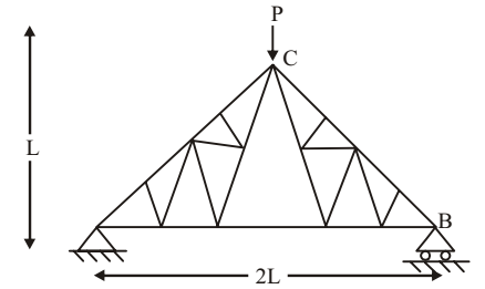
- Force in the member AB of the truss is
-
View Hint View Answer Discuss in Forum
(Method of joints)
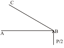
∑ Fx = 0
FBD cos θ + FAB = 0
∑ Fy = 0FBD sin θ + P = 0 2 
- P + 1 + FAB = 0 √2 √2 ∴ FAB = P 2 Correct Option: C
(Method of joints)
∑ Fx = 0
FBD cos θ + FAB = 0
∑ Fy = 0FBD sin θ + P = 0 2 - P + 1 + FAB = 0 √2 √2 ∴ FAB = P 2
Direction: A three span continuaous beam has a internal hinge at B section B is at the mind-span of AC. Section R is at the mid-span of CG. The 20 kN load is applied at section B whereas 10 kN loads are applied at sections D and F as shown in the figure span GH is subjected to uniformly distributed load of magnitude 5 kN/m. For the loading shown shear force immediate to the right of section E is 9.84 kN upwards and the sagging moment at section E is 10.3
AB = BC = 2 m
CD = DE = EF = FG = 1 m
GH = 4M
- The vertical reaction at support H is
-
View Hint View Answer Discuss in Forum
Consider section E H.

∑MG = 0
(RH × 4) + 10.31 – (9.48 × 2) + (10 × 1) – (5 × 4 × 2) = 0
RH = 9.84 kNCorrect Option: B
Consider section E H.
∑MG = 0
(RH × 4) + 10.31 – (9.48 × 2) + (10 × 1) – (5 × 4 × 2) = 0
RH = 9.84 kN
- The magnitude of the shear force immediate to the left and immediate to the right of section B are, respectively
-
View Hint View Answer Discuss in Forum
SF at right of B = 20 kN
SF at left of B = 0Correct Option: A
SF at right of B = 20 kN
SF at left of B = 0
- In a system, two connected rigid bars AC and BC are of identical length L with pin supports at A and B. The bars are interconnected at C by a friction less hinge. The rotation of the hinge is restrained by a rotational spring of stiffness, k. The system initially assumes a straight line configuration, ACB. Assuming both the bars as weightless, the rotation at supports, A and B, due to a transverse load, P applied at C is:
-
View Hint View Answer Discuss in Forum
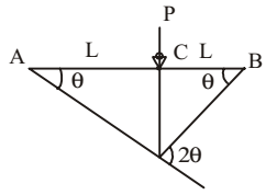
External work = (1/2)P.L θ
Strain energy in spring
=1/2 × k.(2θ)(2θ) = 2 K θ2
External work = strain energy
∴ (1/2)P.L θ = 2 K θ2
∴ θ = PL/4kCorrect Option: A
External work = (1/2)P.L θ
Strain energy in spring
=1/2 × k.(2θ)(2θ) = 2 K θ2
External work = strain energy
∴ (1/2)P.L θ = 2 K θ2
∴ θ = PL/4k
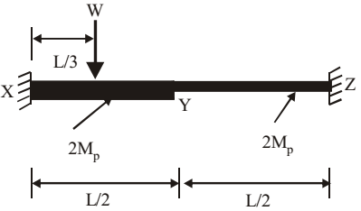
- A fixed end beam is subjected to a load, W at 1/ 3rd span from the left support as shown in the figure. The collapse load of the beam is
-
View Hint View Answer Discuss in Forum
Plastic hinges = 3

α = θ 2
⇒ θ = 2αθ = ∆ L/3 ⇒ ∆ = θ L 3 = 2α L 3
2MPθ + 2MPθ + 2MPα + MPα = W∆
Correct Option: C
Plastic hinges = 3
α = θ 2
⇒ θ = 2αθ = ∆ L/3 ⇒ ∆ = θ L 3 = 2α L 3
2MPθ + 2MPθ + 2MPα + MPα = W∆

