Mechanical and structural analysis miscellaneous
- For formation of collapse mechanism in the following figure, the minimum value of Pu is cmp /L. mp and 3 mp denote the plastic moment capacities of beam sections as shown in this figure. The value of c is________.

-
View Hint View Answer Discuss in Forum
Mechanism I
3mp .θ + mp .(2 θ ) + mp θP u × L × θ 4 
⇒ 6mp .θ = P u × L × θ 4 ⇒ P u = 24 mp L
Mechanism II
1.Φ = 3θ
⇒ Φ = 3θ
= 13.33 mp L
∴ c = 13.33Correct Option: C
Mechanism I
3mp .θ + mp .(2 θ ) + mp θP u × L × θ 4 ⇒ 6mp .θ = P u × L × θ 4 ⇒ P u = 24 mp L
Mechanism II
1.Φ = 3θ
⇒ Φ = 3θ= 13.33 mp L
∴ c = 13.33
- Two beams are connected by a linear spring as shown in the following figure. For a load P as shown in the figure, the percentage of the applied load P carried by the spring is ________.

-
View Hint View Answer Discuss in Forum
∆ = R = R × 2L3 K 3EI ∆ = 
K = 3EI 
2L3 ∆ = 2RL3 3EI 
⇒ P = R 3
∴ % of applied load carried by spring= 1 × 100 = = 33.3% 3 Correct Option: A
∆ = R = R × 2L3 K 3EI ∆ = K = 3EI 2L3 ∆ = 2RL3 3EI ⇒ P = R 3
∴ % of applied load carried by spring= 1 × 100 = = 33.3% 3
- For the 2D truss with the applied loads shown below, the strain energy in the member XY is _______ kN-m. For member XY, assume AE=30kN, where A is cross section area and E is the modulus of elasticity.

-
View Hint View Answer Discuss in Forum

RA × 3 + 10 × 9 = 0
⇒ RA = –30 kN
RB = 35 kN
Taking joint A
Taking joint B
Taking joint x
Fx = 10 kNU = F2 × L 2AE = 102 × 3 = 5 kNm 2 × 3 
Correct Option: A
RA × 3 + 10 × 9 = 0
⇒ RA = –30 kN
RB = 35 kN
Taking joint A
Taking joint B
Taking joint x
Fx = 10 kNU = F2 × L 2AE = 102 × 3 = 5 kNm 2 × 3
- A tapered circular rod of diameter varying from 20 mm to 10 mm is connected to another uniform circular rod of diameter 10 mm as shown in the following figure. Both bars are made of same material with the modulus of elasticity, E = 2 × 10⁵ MPa. When subjected to a load P= 30π kN, the deflection at point A is ________ mm.

-
View Hint View Answer Discuss in Forum

∆1 = PL = 4PL AE πd1d2.E = 4 × 30π × 2 × 106 = 6 mm π × 20 × 10 × 2 × 105 ∆2 = PL AE 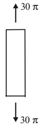
= 4 × 30π × 1.5 × 106 = 9 mm π × 10 × 10 × 2 × 105
∴ ∆ = ∆1 + ∆2 = 15 mmCorrect Option: C
∆1 = PL = 4PL AE πd1d2.E = 4 × 30π × 2 × 106 = 6 mm π × 20 × 10 × 2 × 105 ∆2 = PL AE = 4 × 30π × 1.5 × 106 = 9 mm π × 10 × 10 × 2 × 105
∴ ∆ = ∆1 + ∆2 = 15 mm
- Two Triangular wedges are glued together as shown in the following figure. The stress acting normal to the interface, σn is __ MPa.

-
View Hint View Answer Discuss in Forum
Normal stress, σn
σn = σx + σy + σx - σy cos2θ 2 2 = 100 - 100 + 100 - (-100) cos(2 × 45) 2 2 = 0 + 200 × 0 = 0 2 Correct Option: A
Normal stress, σn
σn = σx + σy + σx - σy cos2θ 2 2 = 100 - 100 + 100 - (-100) cos(2 × 45) 2 2 = 0 + 200 × 0 = 0 2

