Digital circuits miscellaneous
- The circuit shown in the figure given below Output

-
View Hint View Answer Discuss in Forum
NA
Correct Option: A
NA
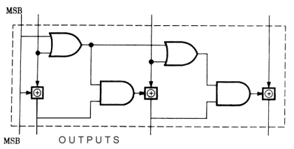
- The circuit shown in the figure converts
-
View Hint View Answer Discuss in Forum
All BCD combination can be convert into binary code except 1000 & 1001. Hence best possible answer is (a).
Correct Option: A
All BCD combination can be convert into binary code except 1000 & 1001. Hence best possible answer is (a).
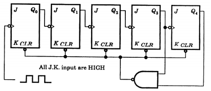
- The mod-number of the asynchronous counter shown in the figure is
-
View Hint View Answer Discuss in Forum
It is a 5 bit ripple counter. At 11000, output of NAND gate is LOW. This will clear all FF. So it is a Mod – 24 counter.
Note that when 11000 occur, the CLR input is activated and all FF are immediately cleared. So it is a MOD 24 counter not MOD 25.Correct Option: A
It is a 5 bit ripple counter. At 11000, output of NAND gate is LOW. This will clear all FF. So it is a Mod – 24 counter.
Note that when 11000 occur, the CLR input is activated and all FF are immediately cleared. So it is a MOD 24 counter not MOD 25.
- The combinational logic circuit shown in the given figure has an output Q which is

-
View Hint View Answer Discuss in Forum
From the K-map,
Q = A + B + C
Correct Option: B
From the K-map,
Q = A + B + C
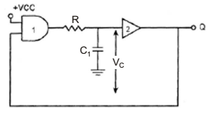
- The stable multivibrator shown in the figure has R = 300Ω and C1 = 500 pƒ The pulse width is
-
View Hint View Answer Discuss in Forum
NA
Correct Option: B
NA

