Digital circuits miscellaneous
- Output Y of the circuit shown in the figure is

-
View Hint View Answer Discuss in Forum

Y = (A + B)C. DE.
= (A + B) C + DECorrect Option: A
Y = (A + B)C. DE.
= (A + B) C + DE
- I n the given network of AND and OR gates, ƒ can be written as

-
View Hint View Answer Discuss in Forum
In terms of Boolean operations
Output of 1 is x0 x1
Output of 2 is (x0 x1 + x2)
Output of 3 is (x0 x1 + x2) x3 = x0 x1 x3 + x2 x3
Output of 4 is x0 x1 x3 + x2 x3 + x4
Output of 5 would be x0 x1 x3 x5 + x2 x3 x5 + x4 x5
Output of 6 would be x0 x1 x3 x5 + x2 x3 x5 + x4 x5 x6
Thus for n gates connected as shown, the output would be
x0 x1 x3 ...................... xn– 1
+ x2 x3 x5 ...................... xn– 1
+ x4 x5 x7 ...................... xn– 1
+ xh – 2 xn– 1
+ xn .Correct Option: D
In terms of Boolean operations
Output of 1 is x0 x1
Output of 2 is (x0 x1 + x2)
Output of 3 is (x0 x1 + x2) x3 = x0 x1 x3 + x2 x3
Output of 4 is x0 x1 x3 + x2 x3 + x4
Output of 5 would be x0 x1 x3 x5 + x2 x3 x5 + x4 x5
Output of 6 would be x0 x1 x3 x5 + x2 x3 x5 + x4 x5 x6
Thus for n gates connected as shown, the output would be
x0 x1 x3 ...................... xn– 1
+ x2 x3 x5 ...................... xn– 1
+ x4 x5 x7 ...................... xn– 1
+ xh – 2 xn– 1
+ xn .
- A carry look ahead adder is frequently used for addition because it
-
View Hint View Answer Discuss in Forum
Carry look ahead adder is after since the carry is generated in parallel at all stages of addition rather than sequentially as in ripple adders.
Correct Option: A
Carry look ahead adder is after since the carry is generated in parallel at all stages of addition rather than sequentially as in ripple adders.
- Output of the circuit shown in the figure is equal to

-
View Hint View Answer Discuss in Forum
The gates are XNOR
F = (A ⊕ B) ⊕ (A ⊕ B) = (AB + AB) ⊕ (AB + AB)
= (AB + AB) ⊕ (A B + AB)
= (AB + AB) ⊕ (AB + AB)
= 0Correct Option: A
The gates are XNOR
F = (A ⊕ B) ⊕ (A ⊕ B) = (AB + AB) ⊕ (AB + AB)
= (AB + AB) ⊕ (A B + AB)
= (AB + AB) ⊕ (AB + AB)
= 0
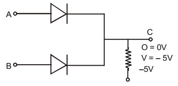
- If negative logic is used, diode gate shown in the given figure will represent a/an
-
View Hint View Answer Discuss in Forum
When either A or B or both are at zero potential, current flows through R, thereby bringing the potential of C to zero level, Thus logic output is zero. When both of them are at 5V no current can flow and voltage of C stays at – 5V, i.e. logic output of 1.

Thus it is AND gate.Correct Option: B
When either A or B or both are at zero potential, current flows through R, thereby bringing the potential of C to zero level, Thus logic output is zero. When both of them are at 5V no current can flow and voltage of C stays at – 5V, i.e. logic output of 1.
Thus it is AND gate.

