Digital circuits miscellaneous
- A state diagram of a logic gate which exhibits a delay in the output is shown in the figure, where X is the don’t care condition, and Q is the output representing the state.
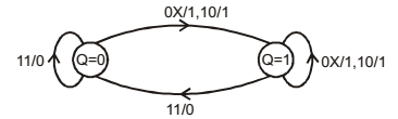
The logic gate represented by the state diagram is
-
View Hint View Answer Discuss in Forum

If you will observe this true table corresponding to state diagram, then if any input is 0 output is 1 and if all the inputs are one output is zero it means it corresponds to NAND gate.Correct Option: D
If you will observe this true table corresponding to state diagram, then if any input is 0 output is 1 and if all the inputs are one output is zero it means it corresponds to NAND gate.
- The clock frequency applied to the digital circuit shown in the figure below is 1 kHz. If the initial state of the output Q of the flip-flop is ‘0', then the frequency of the output wave orm Q in kHz is X

-
View Hint View Answer Discuss in Forum
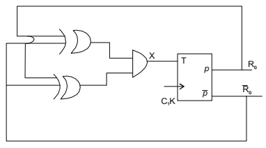
From above fig.
X = [(Q ⊕ Q).(Q ⊕ Q)]
X = 1 because
Q ⊕ Q = 1 always ⇒ Q ⊕ Q = 0 always
∴ (q ⊕ Q) . (Q ⊕ Q = (1 . 0) = 0 = 1
∴ ‘ T ’ input = 1 always for ‘τ’ flip flop of input = 1 then O/P will be implemented at the time of triggering.
∴ ƒ1 = 0.5(ƒ) = 0.5(1) = 0.5kHzCorrect Option: B
From above fig.
X = [(Q ⊕ Q).(Q ⊕ Q)]
X = 1 because
Q ⊕ Q = 1 always ⇒ Q ⊕ Q = 0 always
∴ (q ⊕ Q) . (Q ⊕ Q = (1 . 0) = 0 = 1
∴ ‘ T ’ input = 1 always for ‘τ’ flip flop of input = 1 then O/P will be implemented at the time of triggering.
∴ ƒ1 = 0.5(ƒ) = 0.5(1) = 0.5kHz
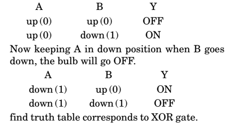
- A bulb in a staircase has two switches, one switch being at the ground floor and the other one at the first floor. The bulb can be turned ON and also can be turned OFF by any one of the switches irrespective of the state of the other switch. The logic of switching of the bulb resembles
-
View Hint View Answer Discuss in Forum
Let us consider the switches A and B and bulb Y. Switches can be 2 positions up (0) or down (1) Starting with both A and B in up position. Let the bulb be OFF. N ow since B can oper at e independently when B goes down, the bulb goes ON
Correct Option: C
Let us consider the switches A and B and bulb Y. Switches can be 2 positions up (0) or down (1) Starting with both A and B in up position. Let the bulb be OFF. N ow since B can oper at e independently when B goes down, the bulb goes ON
- The output Y of a 2-bit comparator is logic 1 whenever the 2-bit input A is greater than the 2-bit input B. The number of combinations for which the output is logic 1, is
-
View Hint View Answer Discuss in Forum

Correct Option: B
- A JK flip flop can be implemented by T flip-flops. Identify the correct implementation.
-
View Hint View Answer Discuss in Forum

Analysis : If you will observe the combinational circuit output expression which is the input for T flip flop is not matching directly, so you should go through the option. If you will solve the combinational circuit of option (B) then
T = (J Qn).(K + Qn)
= J.K + JQn + K.Qn + Qn Qn
= J.K + JQn + K.Qn 0
(∵ Qn. Qn = 0)
= J.K + JQn K.Qn
Now, according to consensus theorem J-K will become redundant term, so it should be eliminated.
Hence, T = JQn + K.Qn which in matching with our desired result and option-(b) is correct answer.Correct Option: B
Analysis : If you will observe the combinational circuit output expression which is the input for T flip flop is not matching directly, so you should go through the option. If you will solve the combinational circuit of option (B) then
T = (J Qn).(K + Qn)
= J.K + JQn + K.Qn + Qn Qn
= J.K + JQn + K.Qn 0
(∵ Qn. Qn = 0)
= J.K + JQn K.Qn
Now, according to consensus theorem J-K will become redundant term, so it should be eliminated.
Hence, T = JQn + K.Qn which in matching with our desired result and option-(b) is correct answer.

