Network theory miscellaneous
- In figure, the value of the source voltage is—
-
View Hint View Answer Discuss in Forum
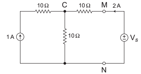
The given figure
Applying KCL at node C, we get= VC - 0 = 1 + 2 10
or
VC = 30V
and= Vs - VC = 2 10
or
VS = 20 + Vc = 20 + 30
= 50V
Hence alternative (C) is the correct choice.Correct Option: C
The given figure
Applying KCL at node C, we get= VC - 0 = 1 + 2 10
or
VC = 30V
and= Vs - VC = 2 10
or
VS = 20 + Vc = 20 + 30
= 50V
Hence alternative (C) is the correct choice.
- In figure, the value of R is—
-
View Hint View Answer Discuss in Forum
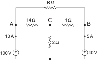
The given circuit:
Applying KCL at node C,= VC - VA + VC - VB + VC = 0 14 1 2
orVc 
1 + 1 + 1 
= VA + VB = 100 + 40 14 1 2 14 1 14 1
orVc 1 + 14 + 7 = 100 + 40 × 14 14 14
or
VC = 30V
Now, current in 14Ω resistor,I14Ω = 100 - VC = 100 - 30 14 14
= 5A
So,
IR = 10 – 5 = 5A
andR = VA - VB = 100 - 40 IR 5
or
R = 60/5 ≈ 12Ω
Hence alternative (D) is most correct choice.Correct Option: A
The given circuit:
Applying KCL at node C,= VC - VA + VC - VB + VC = 0 14 1 2
orVc 1 + 1 + 1 = VA + VB = 100 + 40 14 1 2 14 1 14 1
orVc 1 + 14 + 7 = 100 + 40 × 14 14 14
or
VC = 30V
Now, current in 14Ω resistor,I14Ω = 100 - VC = 100 - 30 14 14
= 5A
So,
IR = 10 – 5 = 5A
andR = VA - VB = 100 - 40 IR 5
or
R = 60/5 ≈ 12Ω
Hence alternative (D) is most correct choice.
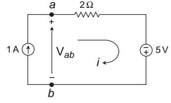
- Assuming ideal elements in the circuit shown below, the voltage Vab will be—
-
View Hint View Answer Discuss in Forum
The given circuit:

Applying KVL in the loop, we get,
Vab – 2 × 1 + 5 = 0
or
Vab = 2 – 5
= – 3V.Correct Option: A
The given circuit:
Applying KVL in the loop, we get,
Vab – 2 × 1 + 5 = 0
or
Vab = 2 – 5
= – 3V.
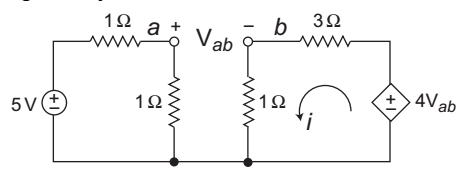
- In the circuit shown in the figure, the value of the current i will be given by—
-
View Hint View Answer Discuss in Forum
The given circuit:
Va = 5 × 1 = 5 V 1 + 1 2 Vb = 4Vab × 1 = Vab 1 + 3 4
Vab = Va – Vb = 5/2 – Vab
or
2Vab = 5/2
or
Vab = 5/4 V
or
Vab = 1.25 V
andi = 4 × Vab = 4 × 1.25 = 1.25A 4 4
Hence alternative (B) is the correct choice.Correct Option: A
The given circuit:
Va = 5 × 1 = 5 V 1 + 1 2 Vb = 4Vab × 1 = Vab 1 + 3 4
Vab = Va – Vb = 5/2 – Vab
or
2Vab = 5/2
or
Vab = 5/4 V
or
Vab = 1.25 V
andi = 4 × Vab = 4 × 1.25 = 1.25A 4 4
Hence alternative (B) is the correct choice.
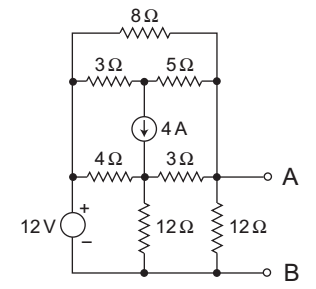
- What is the Thevenin resistance seen from the terminals AB of the circuit shown above in the figure?
-
View Hint View Answer Discuss in Forum
The given circuit:
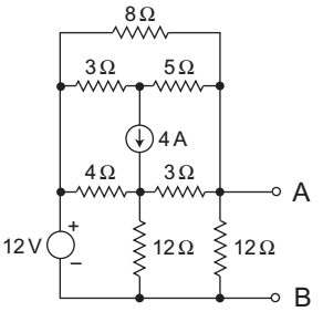
The equivalent circuit for calculation of Rth is shown below—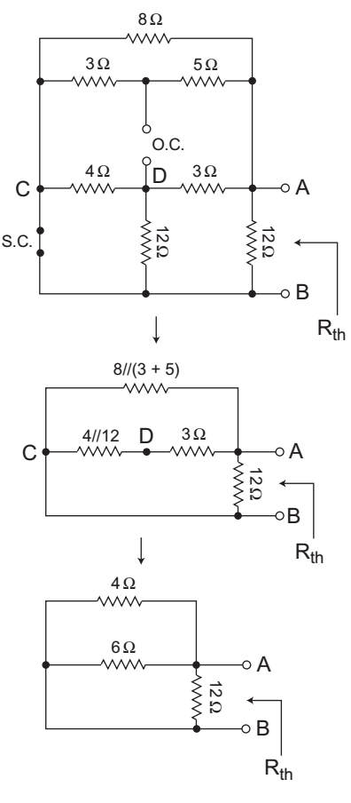
Now, from above figure1 = 1 + 1 + 1 Rth 4 6 12
or1 = 3 + 2 + 1 Rth 12
orRth = 12 = 2Ω 6
Hence alternative (A) is the correct choice.Correct Option: A
The given circuit:
The equivalent circuit for calculation of Rth is shown below—
Now, from above figure1 = 1 + 1 + 1 Rth 4 6 12
or1 = 3 + 2 + 1 Rth 12
orRth = 12 = 2Ω 6
Hence alternative (A) is the correct choice.

