Electrical and electronics measurements miscellaneous
- For the switching converter shown in the following figure, assume steady-state operation. Also assume that the components are ideal, the inductor current is always positive and continuous and switching period is T5. If the voltage VL is as shown, the duty cycle of the switch S is ________.

-
View Hint View Answer Discuss in Forum
VS = 15V
V0 = VS = - 45
V0 = VV + 45
= (15 + 45) V = 60VNow, V0 = VS = % 1 - D ∴ 60 = 15 = % 1 - D
∴ 60(1 – D) = 15∴ 1 - D = 1 4 ∴ D = 3 = 0.75 4 Correct Option: C
VS = 15V
V0 = VS = - 45
V0 = VV + 45
= (15 + 45) V = 60VNow, V0 = VS = % 1 - D ∴ 60 = 15 = % 1 - D
∴ 60(1 – D) = 15∴ 1 - D = 1 4 ∴ D = 3 = 0.75 4
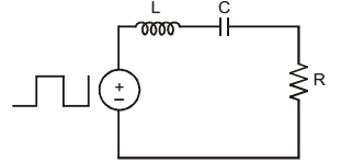
- A symmetrical square wave of 50% duty cycle has amplitude of ± 15V and time period of 0.4π ms. This square wave is applied across a series RLC circuit with R = 5Ω, L = 10 mH, and C = 4μF. The amplitude of the 5000 rad/s component of the capacitor voltage (in Volt) is _________.

-
View Hint View Answer Discuss in Forum
NA
Correct Option: A
NA
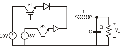
- The circuit shown in meant to supply a resistive load RL from two separate DC voltage sources. The switches S1 and S2 are controlled so that only one of them is ON at any instant. S1 is turned on for 0.2 ms and S2 is turned on for 0.3 ms in a 0.5 ms switching cycle time period. Assuming continuous conduction of the inductor current and negligible ripple on the capacitor voltage, the output voltage Vo (inVolt) across RL is ________.

-
View Hint View Answer Discuss in Forum

V0 = 10 × 0.2 + 5 × 0.3 = 7 V 0.5 Correct Option: C

V0 = 10 × 0.2 + 5 × 0.3 = 7 V 0.5
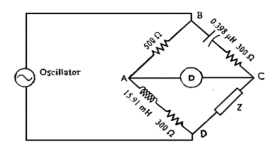
- The ac bridge shown in the figure given below is used to measure the impedance Z.
If the bridge is balanced for oscillator frequency f = 2 kHz, then impedance Z will be
-
View Hint View Answer Discuss in Forum
XL = 2πfL
= 2π × 2000 × 15.91 × 10–3
XC = 1 2πfC = 1 = 200Ω 2π × 2000 × 0.398 × 10-6
Under balanced condition
Z1 Z4 = Z2 Z3
⇒ R1 (R4 + jX4) = (R2 + jX2) (R3 – jX3)
⇒ 500(R4 + jX4) = (300 + j200) (300 – j200)
⇒ 500(R4 + jX4) = 90000 + 40000⇒ R4 + jR4 = 130000 = 260 500
⇒ Z = 260 + j0
AlternatelyAt balance ZAB = ZBC ZAD ZCD or, 500 = R + (1/jωc) R + jωL Z or Z = (R + jωL)(R + 1/jωc) = (300 + j2 × 10³ × 3.14 × 2 × 15.91 × 10-3) 500 = 300 - j/2 × 3.14 × 103 × 2 × 0.398 × 10-6 = % 500 = (300 + j199.82)(300 - j200) 500
≈ (260 + j0)ΩCorrect Option: A
XL = 2πfL
= 2π × 2000 × 15.91 × 10–3
XC = 1 2πfC = 1 = 200Ω 2π × 2000 × 0.398 × 10-6
Under balanced condition
Z1 Z4 = Z2 Z3
⇒ R1 (R4 + jX4) = (R2 + jX2) (R3 – jX3)
⇒ 500(R4 + jX4) = (300 + j200) (300 – j200)
⇒ 500(R4 + jX4) = 90000 + 40000⇒ R4 + jR4 = 130000 = 260 500
⇒ Z = 260 + j0
AlternatelyAt balance ZAB = ZBC ZAD ZCD or, 500 = R + (1/jωc) R + jωL Z or Z = (R + jωL)(R + 1/jωc) = (300 + j2 × 10³ × 3.14 × 2 × 15.91 × 10-3) 500 = 300 - j/2 × 3.14 × 103 × 2 × 0.398 × 10-6 = % 500 = (300 + j199.82)(300 - j200) 500
≈ (260 + j0)Ω
- Match the following:
Instrument Type Used for P. Permanent magnet moving coil 1. DC only Q. Moving iron connected through current transformer 2. AC only R. Rectifier 3. AC and DC S. Electrodynamometer
-
View Hint View Answer Discuss in Forum
NA
Correct Option: C
NA

