Electric circuits miscellaneous
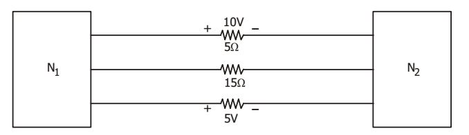
- The two electric sub-networks N1 and N2 are connected through three resistors as shown in the figure below. The voltage across 5 Ω resistor and 1 Ω resistor are given to be 10V and 5V respectively. Then voltage across 15 Ω resistor is
-
View Hint View Answer Discuss in Forum
By KCL, if we take a cutset along all three branches, then total current at the junction is zero.
i.e. I 1 + I 2 + I 3 = 0⇒ 10 + I2 + 5 = 0 5 1
⇒ I2 = 7A
and V = – 105 V.Correct Option: A
By KCL, if we take a cutset along all three branches, then total current at the junction is zero.
i.e. I 1 + I 2 + I 3 = 0⇒ 10 + I2 + 5 = 0 5 1
⇒ I2 = 7A
and V = – 105 V.
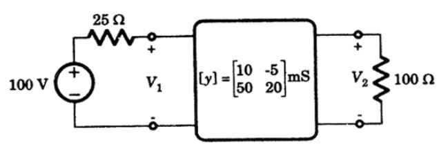
- In the given circuit, voltages V1 and V2 respectively are
-
View Hint View Answer Discuss in Forum
I1 = 10 × 10– 3 V1 – 5 × 10– 3V2
100 = 25I1 + V1
100 – V1 = 0.25V1 – 0.125 V2
⇒ 800 = 10 V2....(i)
I 2 = 50 × 10– 3 V1 + 20 × 10– 3V2
V2 = – 100 I2
∴ V2 = 5V1 – 2V2
⇒ 3V2 + 5V1 = 0 ....(ii)
Solving equations (i) and (ii), we get
V1 = 68.6 V, and V2 = – 114.3 VCorrect Option: B
I1 = 10 × 10– 3 V1 – 5 × 10– 3V2
100 = 25I1 + V1
100 – V1 = 0.25V1 – 0.125 V2
⇒ 800 = 10 V2....(i)
I 2 = 50 × 10– 3 V1 + 20 × 10– 3V2
V2 = – 100 I2
∴ V2 = 5V1 – 2V2
⇒ 3V2 + 5V1 = 0 ....(ii)
Solving equations (i) and (ii), we get
V1 = 68.6 V, and V2 = – 114.3 V
- A T-network is shown in the given figure. Its Y matrix will be (units in siemens)

-
View Hint View Answer Discuss in Forum
NA
Correct Option: C
NA
- The driving-point impedance of a one-port reactive network is given by
-
View Hint View Answer Discuss in Forum
For an L– C network, driving-point impedance function poles and zeros should alternate. This is satisfied by the function at (b) alone.
Correct Option: B
For an L– C network, driving-point impedance function poles and zeros should alternate. This is satisfied by the function at (b) alone.
-
In the circuit shown in the given figure, G12 = V2 = ? V1 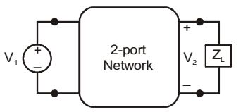
-
View Hint View Answer Discuss in Forum
I2 = y21V1 + y22V2
I2 = – V2 YL
y21V1 + (y22 + YL )V2 = 0∴ V2 = -y21 V1 (y22 + yL)
Correct Option: B
I2 = y21V1 + y22V2
I2 = – V2 YL
y21V1 + (y22 + YL )V2 = 0∴ V2 = -y21 V1 (y22 + yL)

