-
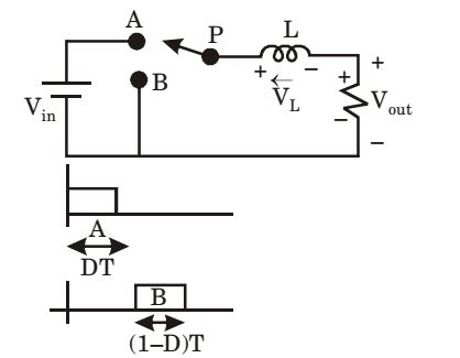
The power electronic converter shown in the figure given below has a single-pole double-throw switch. The pole P of the switch is connected alternately to throws A and B. The converter shown is a

-
- step-down chopper (buck converter)
- half-wave rectifier
- step-up chopper (boost converter)
- full-wave rectifier
Correct Option: A

Let Duty cycle be ‘D’.
When at A : t = 0
| Vin = L | + Vout , (iL)in = | DT | ||
| dt | L |
When at B : At t = DT
| Vout = -VL = | ||
| dt |
| (iL)off = | (1 - D)T | |
| L |
(Vin – Vout) DT + (– Vout) (1 – D)T = 0
⇒ (Vin – Vout) D = Vout(1 – D)
⇒ Vout = DVin and D < 1
So, step down chopper.

