Academic Resource
Aptitude
Data Interpretation
Verbal Reasoning
Non Verbal Reasoning
Verbal Ability
Programming
General Knowledge
Puzzle
Engineering
Computer Engineering
Electronics and Communication
Electrical Engineering
Mechanical Engineering
Civil Engineering
Biotechnology
Architecture & Planning
Online Test
Aptitude Test
Data Interpretation Test
Verbal Reasoning Test
Non Verbal Reasoning Test
Verbal Ability Test
Exams
More
Full Forms
Home
»
Power Electronics
»
Power electronics miscellaneous
» Question
Power electronics miscellaneous
Easy Questions
Moderate Questions
Difficult Questions
Power Electronics
Power electronics miscellaneous
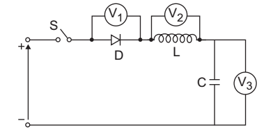
In given fig., V
1
, V
2
and V
3
are zero centre PMMC voltmeters. The circuit is initially relaxed. Switch S is closed at t = 0. In steady state, readings of voltmeters V
1
, V
2
and V
3
are respectively:
100 V, 100 V, – 100 V
100 V, 0, 200 V
– 100 V, 0, 200 V
100 V, 0, 100 V
Correct Option:
C
NA
Previous Question
Next Question
Your comments will be displayed only after manual approval.
Post your Comment