-
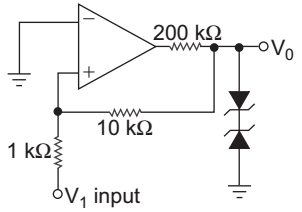
Figure shown a Schmitt trigger circuit op-amp. The output V0 is limited to + 10 V and – 5 V connecting suitably chosen Zener diodes at the output. The lower and upper trigger voltage are respectively:

-
- – 1 V and 0.5 V
- – 0.5 V and 1.0 V
- – 1 V and – 0.5 V
- 0.5 V and 1.0 V
Correct Option: A
| VUT = – (– Vsat). | = – (– 5). | = 0.5 V | ||
| dR | 10 |
| VLT = – Vsat. | = – 10. | = – 1 V | ||
| dR | 10 |

